


Hearth & Home Technologies • GFK21B Fan Kit • 4016-096 Rev I • 11/08
4
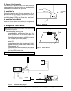
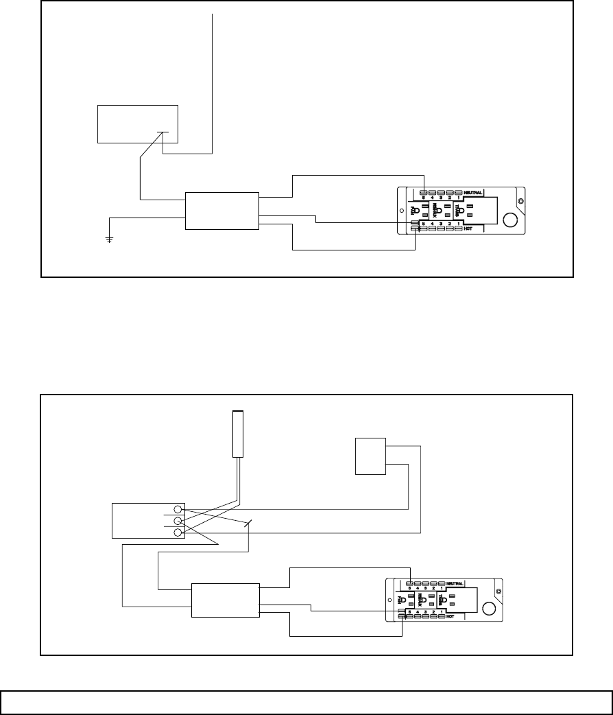
• Dexen Valve (IPI)
- Connect the black, white and red wires with 1/4 in. female connectors from fan control module to appliance junction
box as shown in Figure 10.
- Connect the black ground wire to the appliance.
- Remove the green ignition control wire from the valve.
- Connect the black with white stripe wire with 3/16 in. piggyback connector from fan control module to valve.
- Connect green ignition control wire to piggyback connector on black with white stripe fan control module wire.
Dexen
Valve
Fan
Control
Module
Green Wire from Ignition Control
Black
Black/White
Black
Red
White
Ground
Figure 10 - Dexen (IPI) Wiring Diagram
6. Recommended Fan Control Set-up Procedure
Note: The test sequence works only during the fi rst (approximately) seven minutes after power-up.
• With burner and pilot extinguished:
• Turn control knob clockwise to activate control.
• Press and hold test button on the control module.
- Fan will turn on.
- Adjust fan speed with control knob.
- Release test button. Fan will stop.
• Light burner.
• Press and release test button.
- Fan will come on at set speed
- After one minute fan will stop.
• Extinguish burner.
• Fan control is now fully operational and will operate
automatically each time appliance is used.
• Operates with APPROXIMATELY a 7-minute delay to turn
on and a 12-minute delay to turn off.
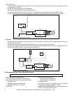
• SIT Valve
- Connect the black, white and red wires with 1/4 in. female connectors from fan control module to appliance junction
box as shown in Figure 11.
- Connect the black ground wire with the ring terminal to the TP screw on the valve (center).
- Connect blue jumper wire between fan control wire (black with white stripe) and valve. Plug 1/4 in. female end of blue
jumper wire to the back side of valve wiring block marked TH.
Wall
Switch
SIT
Valve
TP
TH
TH
TP
Fan
Control
Module
Black/White
Black
Black
Red
White
Thermopile
Red
White
Blue
Ground
Figure 11 - SIT Wiring Diagram