


Heatilator • GDST5244I • 4045-127 • Rev W • 11/0846
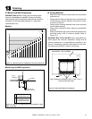
Latches
(both bottom
and top)
Glass
Assembly
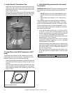
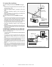
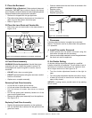
K. Air Shutter Setting
Air shutter settings should be adjusted by a qualifi ed
installer at the time of installation. The air shutter is set at
the factory for minimum vertical vent run. Adjust air shut-
ter for longer vertical runs. See Figure 14.12.
• Turn the shutter adjustment handle to the right to
open.
• Turn the shutter adjustment handle to the left to close.
• It takes 16 full turns to move the air shutter from fully
open to fully closed.
NOTICE: If sooting occurs, provide more air by opening
the air shutter.
Figure 14.12 Air Shutter
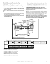
Figure 14.11 Fixed Glass Assembly
H. Fixed Glass Assembly
WARNING! Risk of Asphyxiation! Handle fi xed glass
assembly with care. Inspect the gasket to ensure it is
undamaged and inspect the glass for cracks, chips or
scratches.
• DO NOT strike, slam or scratch glass.
• DO NOT operate fi replace with glass removed, cracked,
broken or scratched.
• Replace as a complete assembly.
J. Install Trim and/or Surround
• Install optional trim kits and/or surrounds using the
instructions included with the accessory.
• Use non-combustible materials to cover the gap between
the sheet rock and the appliance.
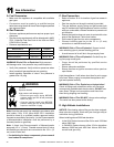
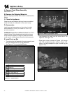
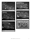
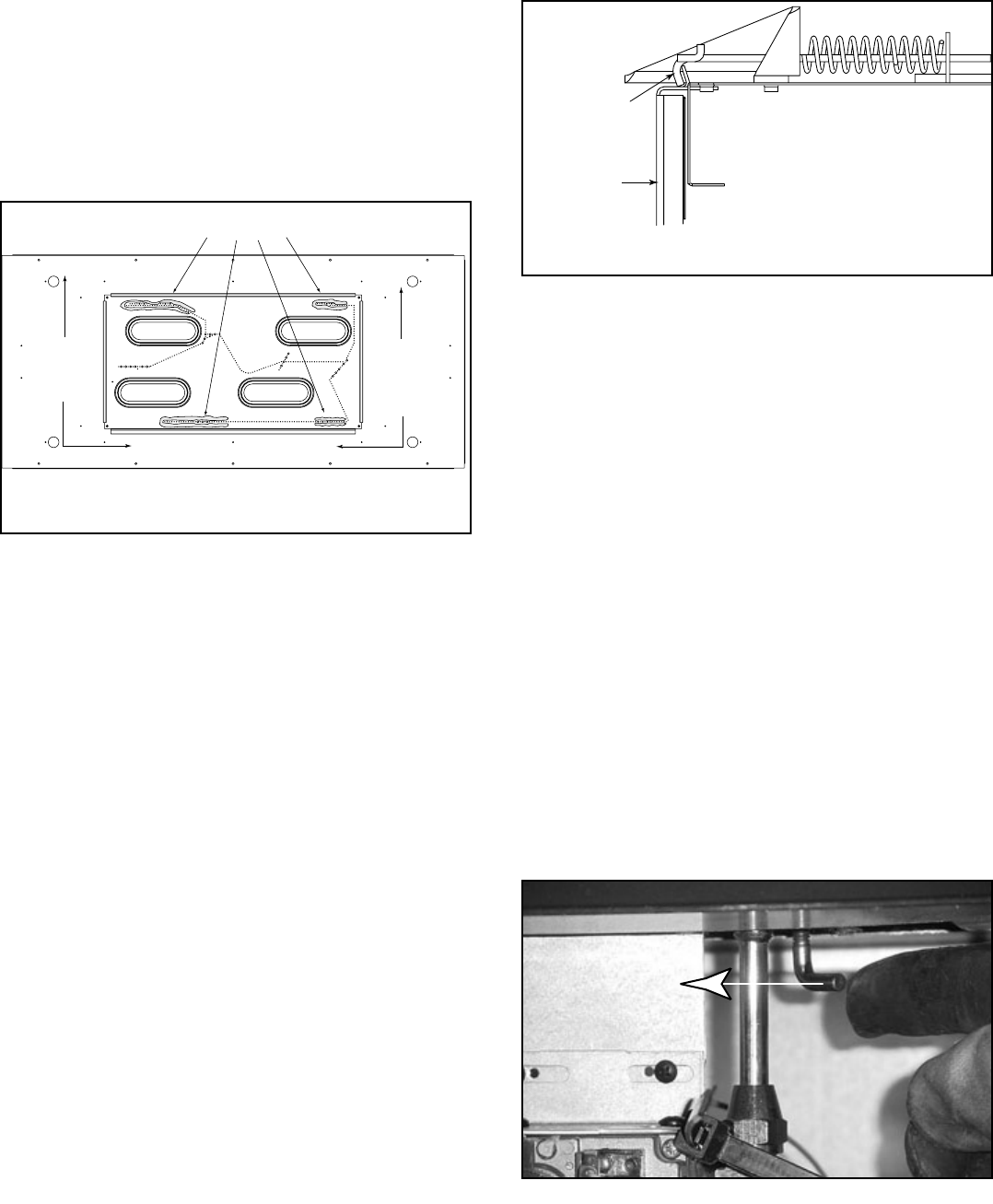
Rock wool placement
(shaded areas)
Vermiculite and
lava rock
placement on
sides and front of
hearth pan.
Vermiculite and
lava rock
placement on
sides and front of
hearth pan.
Figure 14.10 Placement of Rockwool, Lava Rock, Vermiculite
F. Place the Rockwool
WARNING! Risk of Explosion! Follow rockwool placement
instructions. DO NOT place rockwool directly over burner
ports. Replace rockwool material annually. Improperly placed
rockwool interferes with proper burner operation.
• Rockwool is shipped with this gas appliance.
• Place dime-size pieces on burner pan so it touches, but
does not cover the holes in the burner pan.
• Refer to Figure 14.10.
G. Place the Lava Rock and Vermiculite
• Place lava rock and vermiculite in the areas shown in
Figure 14.10.
Replacing Fixed Glass Assembly
• Replace the glass panel assembly on the appliance.
• Pull out and latch the six latches into the groove on the
glass door frame.
Removing Fixed Glass Assembly
• Lift up and out on upper grill to remove.
• Lift up and rotate out access door on bottom.
• Pull out bottom of screen then down to remove
screen.
• Pull the six glass panel assembly latches out of the
groove on the glass frame.
• Remove the glass panel assembly from the appliance.
See Figure 14.11.
I. Firescreen
A screen protective barrier is supplied as a standard
feature. This barrier must be in place when the appliance
is in operation.
Closed
• Check to make certain the door frame is centered in the
glass door opening.
• Replace screen.
• Close access door.
• Replace upper grille.