


Heatilator • GDST3831I • 2127-900 Rev. F • 10/08 45
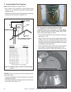
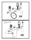
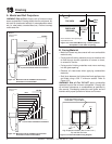
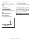
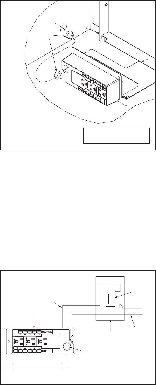
F. Wall Switch Installation for Fan (Optional)
If the box is being wired to a wall mounted switch for use
with a fan (See Figure 12.5):
• The power supply for the appliance must be brought into
a switch box.
• The power can then be supplied from the switch box
to the appliance using a minimum of 14-3 with ground
wire.
• At the switch box connect the black (hot) wire and red
(switch leg) wire to the wall switch as shown.
• At the appliance connect the black (hot), white (neutral)
and green (ground) wires to the junction box as
shown.
• Add a 1/4 in. insulated female connector to the red
(switch leg) wire, route it through the knockout in the face
of the junction box, and connect to the top fan switch
connector (1/4 in. male) as shown.
RED
SWITCH
SWITCH BOX
RED
BLACK
BLACK
GREEN
GREEN
WHITE
POWER
SUPPLY
WIRES
WHITE
RED
BLACK
GREEN
WHITE
MINIMUM 14-3 AWG
WITH GROUND
JUNCTION BOX
KNOCKOUT
Figure 12.5 Junction Box Wired to Wall Switch or BC10
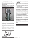
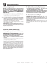
ROMEX CONNECTORS
Figure 12.4 Junction Box Detail
NOTICE: DO NOT wire
110 VAC to wall switch.
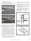
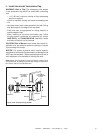
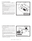
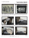
E. Junction Box Installation
The junction box must be wired from the INSIDE of the
appliance:
• Determine which side of the appliance the junction box
is located on.
• Pull the electrical wires from outside the appliance through
the knockout making sure to use a Romex connector to
fasten the electrical wires to the unit.
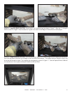
• Pull enough wire into the valve compartment to easily
reach the junction box location.
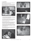
• Remove the screw attaching the junction box to the junction
box bracket and set it aside.
• Route the wire through the knockout in the junction box
bracket.
• Wire the junction box and reattach it to the bracket by
inserting the tab in the slot and attaching with screw
previously removed. Ensure that a Romex connector is
used to attach the electrical wires to the junction box.