


September 1, 2008
Page 15Quadra-Fire · Garnet-T · 7016-127F
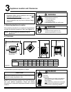
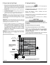
Step 1.
Check the installation instructions for required 1 in. (25mm)
clearances (air space) to combustibles when passing
through ceilings, walls, roofs, enclosures, attic rafters, or
other nearby combustible surfaces. See page 17, Figure
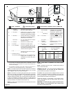
5.16. Check the instructions below for maximum vertical rise
of the venting system, and any maximum horizontal offset
limitations. All offsets must fall within the set parameters of
the vent graph (Figure 5.2) located on page 11.
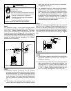
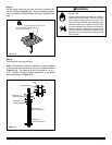
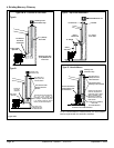
NOTE: Maximum vertical rise allowable is 25 ft. (8m) Figure
5.11).
NOTE: Maximum number of 45° elbows permitted for a
vertical installation is eight, provided their installation
does not decrease maximum allowable horizontal run (as
specified by vent graph, on page 11).
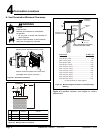
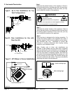
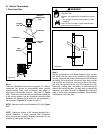
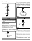
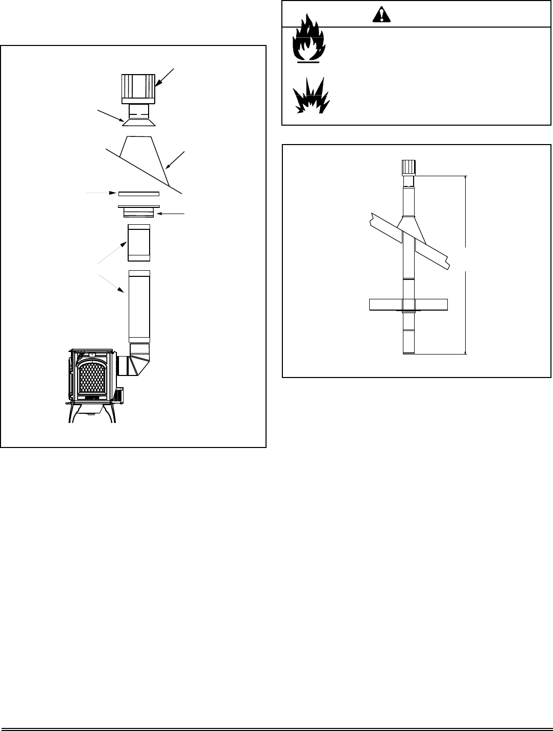
G. Vertical Termination
1. Direct Vent Pipe
Figure 5.10
VERTICAL
TERMINATION
CAP
STORM
COLLAR
FLASHING
FIRESTOP
PIPE
LENGTH
SUPPORT
BOX
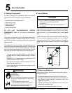
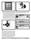
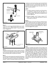
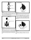
Step 2.
Set the gas appliance in its desired location. Drop a plumb
bob down from the ceiling to the position of the appliance
flue exit, and mark the location where the vent will penetrate
the ceiling. Drill a small hole at this point. Next, drop a plumb
bob from the roof to the hole previously drilled in the ceiling,
and mark the spot where the vent will penetrate the roof.
Determine if ceiling joists, roof rafters, or other framing will
obstruct the venting system. You may wish to relocate the
appliance, or to offset, as shown in Figure 5.12, on the next
page, to avoid cutting loadbearing members. When location
is determined, drill small hole.
Figure 5.11
25 ft. (8m)
MAXIMUM
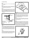
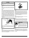
Fire Risk.
Explosion Risk.
Maintain vent clearance to combustibles as speci-
fied.
WARNING
• Do not pack air space with insulation or other
materials.
Failure to keep insulation or other materials away
from vent pipe may cause fire.