


41
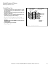
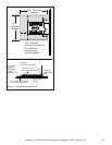
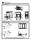
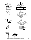
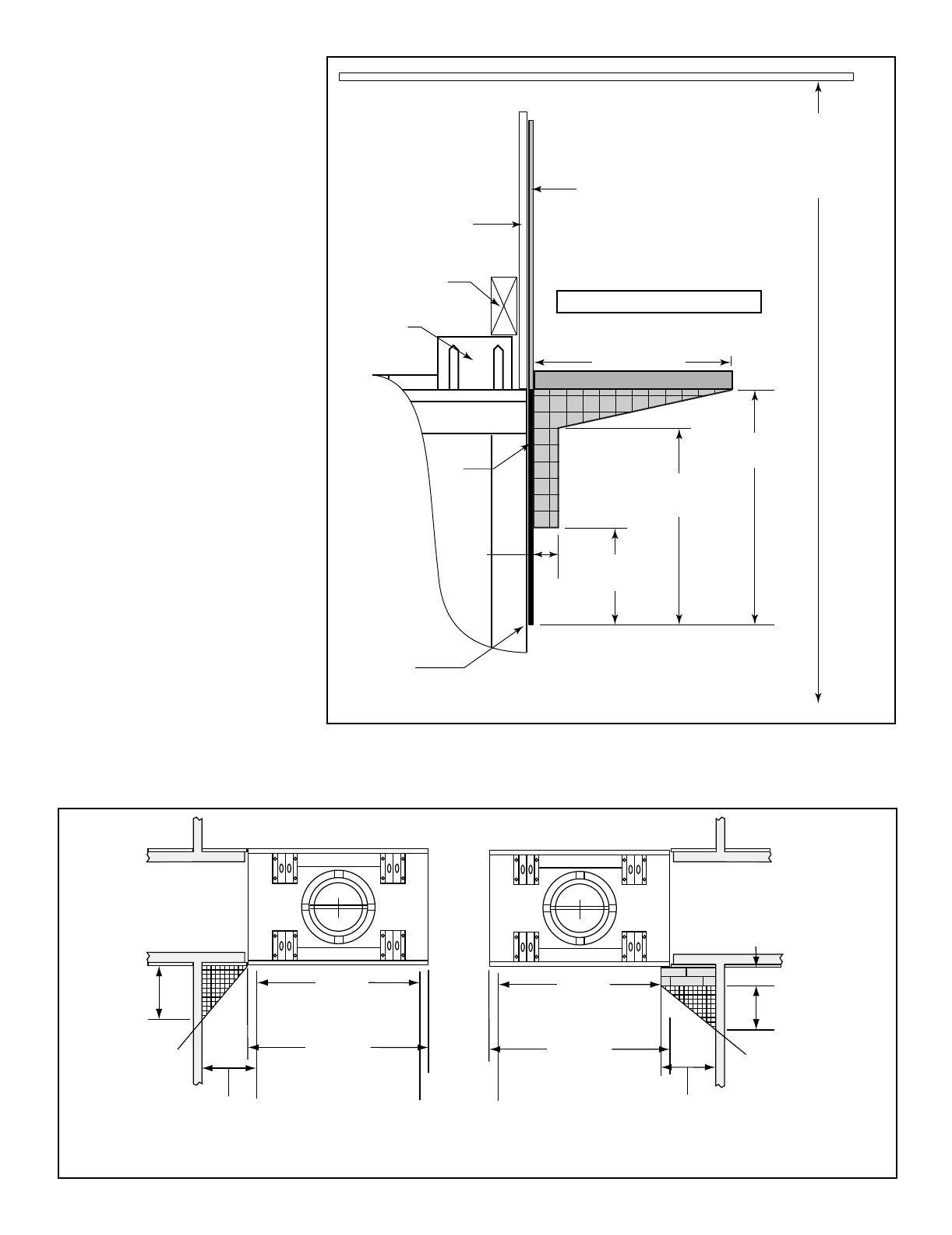
E. Combustible Mantel
• Refer to the shaded areas of Figure
11.4 for locations and dimensions
of a combustible mantel.
• A combustible mantel may be
positioned no lower than 14 1/4 in.
(362 mm) above the top of the
replace opening.
• A combustible mantel may have
a maximum depth of 12 in. (305
mm).
• Combustible trim and materials
cannot be placed within 6 in.
(152mm) of the replace opening
(top or sides).
• Combustible materials projecting
more than 1 1/2 in. (38 mm) shall
not be placed within 12 in. (305
mm) from the top of the replace
opening.
• Combustible trim must not cover the
metal surfaces of the replace.
• Mantel clearance is in accordance
with Section 7-3.3.3 of ANSI/
NFPA211.
7 ft (2134 mm)
minimum
base of fireplace
to ceiling
Combustible Wall
2 x 4 stud wall
Standoffs
Measured from top of fireplace opening
12 in./305 mm
Mantel
1 1/2 in./38 mm
maximum
6 in./152 mm
minimum
14 1/4 in./362 mm
minimum
12 in./305 mm
minimum
Combustible
Decorative Facing
Non-combustible
Decorative Facing
such as: Steel, iron,
brick, tile, concrete,
slate, tile, plasters
Seal joint with
non-combustible
sealant
Grid represents 1 in. squares
Figure 11.4 Clearances to Mantels or other Combustibles above Fireplace
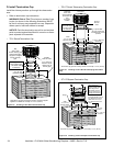
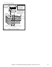
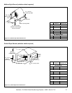
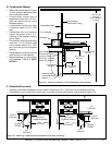
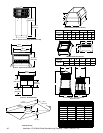
F. Sidewalls/Surrounds
• Adjacent combustible sidewalls must be located a minimum of 12 in. (305 mm) from the replace opening.
• Combustible or non-combustible mantel legs, surrounds and stub walls may be constructed per Figure 11.5.
11.92 in.
[303 mm]
FLUSH
FRONT
40 in.
[1016 mm]
36 in.
[914 mm]
(fireplace opening)
12 in.
[305 mm]
50° angle
9 3/4 in.
[248 mm]
4 in.
[102 mm]
BRICK
FRONT
40 in.
[1016 mm]
36 in.
[914 mm]
(fireplace opening
12 in.
[305 mm]
39° angle
Figure 11.5 Mantel Leg or Wall Projections (acceptable on both sides of opening)
Heatilator • FL92 Multi-Sided Woodburning Fireplace • 34955 • Rev AA 7/12