


Heatilator • Eclipse • 4049-229 Rev F • 11/08 25
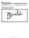
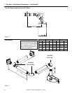
To replace the fi rst starter elbow with two 45° elbows,
refer to Figure 7.4. All other 90° elbows can be replaced
with two 45° elbows.
General Rules:
• SUBTRACT 3 ft. from the total H measurement for each
90° elbow installed horizontally.
• SUBTRACT 1-1/2 ft. from the total H measurement for
each 45° elbow installed horizontally.
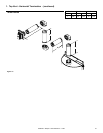
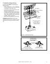
• A maximum of three 90° elbows (or six 45° elbows)
may be used in any vent confi guration. Some elbows
may be installed horizontally. See Figure 7.9.
• Elbows may be placed back to back anywhere in the
system as long as the fi rst 90° elbow is a starter elbow
except as shown in Figure 7.4.
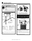
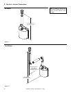
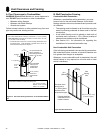
• When penetrating a combustible wall, a wall shield
fi restop must be installed on both sides.
• When penetrating a combustible ceiling, a ceiling
fi restop must be installed.
• Horizontal runs of vent do not require vertical rise;
horizontal runs may be level.
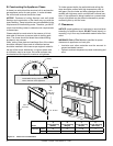
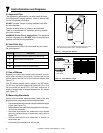
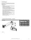
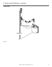
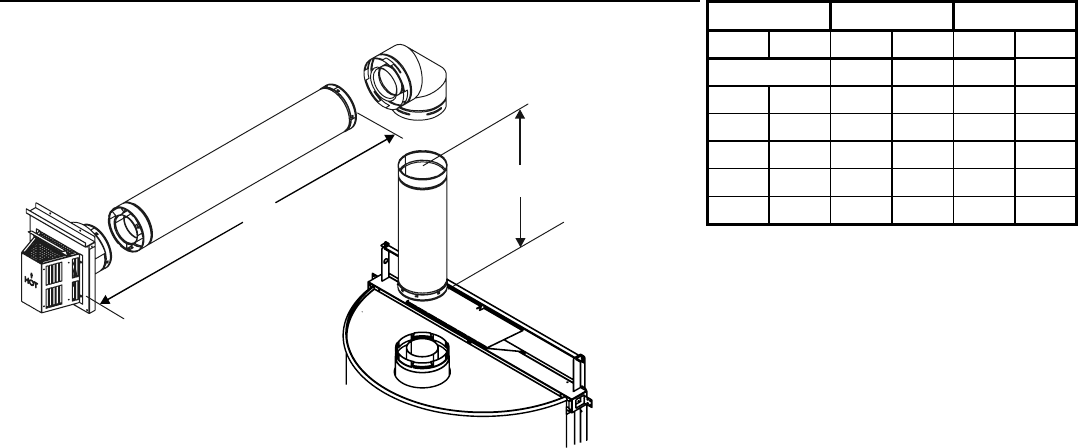
E. Vent Diagrams
Figure 7.3
One Elbow
V
1
H
1
1. Top Vent - Horizontal Termination - (continued)
V
1
min. V
1
max. H
1
max.
ft m ft m ft m
0* - - 1.67 0.51
0.5 0.15 - - 6 1.83
1 0.30 - - 11 3.35
1.5 0.46 - - 18 5.49
2 0.61 - - 25 7.62
- - 25 7.62 25 7.62
* You may install elbow directly on top of appliance.