


08/04 17339 Rev L 19
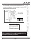
EC SERIES INSTALLATION INSTRUCTIONS
Note: Use only a noncombustible material to finish
the face of the fireplace below the level of the front
standoffs. A noncombustible material such as USG
MICORE CV230 Mineral Fiber Board, or USG
DUROCK Cement Board is recommended for this
purpose.
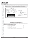
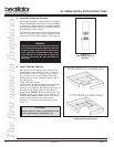
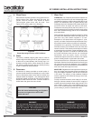
Figure 16 - Air Clearance Around Gas Line
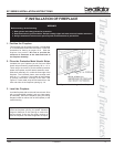
15. Complete the Enclosure
Complete the fireplace enclosure, allowing space for
outside air ducts and gas piping if desired. Electrical
wiring should not come in contact with the fireplace. A
minimum clearance of 1/2 in. must be maintained
between the fireplace sides and the enclosure as
well as the fireplace back and the enclosure. See
pages 10-12 for framing details.
CAUTION:
When using a gas log set, the fireplace damper
must be set in the fully open position. This en-
sures proper venting of combustion products.
WARNING!
This fireplace was not tested by the fireplace
manufacturer for use with an unvented gas log
heater. To reduce risk of injury, do not install an
unvented gas log heater in this fireplace unless
it has been specifically tested and listed by
Underwriter’s Laboratories Inc. for use in this
specific model fireplace. Unless the unvented
gas log heater is tested and listed for use in
this factory built fireplace, a fire hazard may be
created that can result in a structure fire.
16. Gas Log/Lighter Provisions
Knockouts are provided on both sides of the fireplace
to allow for connection of a certified gas log lighter or
a decorative gas appliance with a maximum input of
100,000 BTU/hour, incorporating an automatic gas
shut-off device and complying with the Standard for
Decorative Gas Appliances for Installation in
Vented Fireplaces, ANSI Z21.60. The decorative gas
appliance should be installed in accordance with the
National Fuel Gas Code, ANSI Z223.1-1980. The side
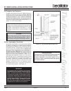
refractories are designed to allow 1/2 in. iron pipe to
pass through. Use a noncombustible sealant to seal
any opening between the gas pipe and refractory on
the inside. Repack the insulation removed to seal
around the gas pipe where it exits the side of the
fireplace. A minimum 1-1/2 in. air clearance must be
provided around the 1/2 in. iron pipe for a minimum of
4 in. beyond the fireplace. See Figure 16.
CLEARANCES!
A minimum 1/2 in. air clearance must be maintained
at the back and sides of the fireplace assembly.
Chimney sections at any level require a 2 in.
minimum air space clearance between the framing
and chimney section.