


10/08
Page 19Quadra-Fire • Columbia Bay • 250-5195 Rev. K
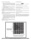
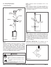
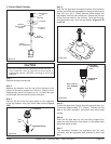
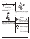
3. Class A Metal Chimney
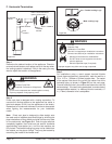
Figure 5.21
Top Adapter
Sheet Metal Screws
Flex
Pipe
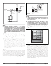
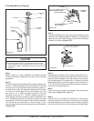
HIGH WIND
TERMINATION
CAP
SHEET METAL
SCREWS
DRILL FOUR 1/8 in.
(3mm) DIAMETER
HOLES
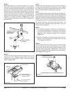
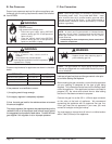
Figure 5.22
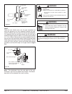
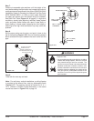
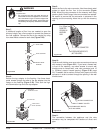
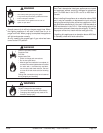
Figure 5.23
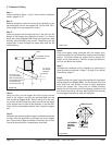
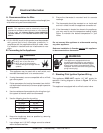
Figure 5.24
Step 1.
Remove existing chimney cap.
Step 2.
Measure the distance from the top of the chimney to the
bottom of the ceiling support box, add 3 in. (76mm) to this
measurement, and cut a section of 4 in. (101mm) flex pipe
to that length (the flex should be fully extended).
Step 3.
Connect the end of the flex pipe section to the underside
of the top adapter, using four sheet metal screws (Figure
5.22).
Step 4.
Pass the flex pipe down through the center of the chimney
system, and center the top adapter on the top of the chimney
pipe. Drill four 1/8 in. (3mm) diameter holes through the
top adapter, and into the chimney top. Ensure that you are
drilling into the metal on the chimney. Twist lock the high
wind termination cap onto the top adapter (Figures 5.23
and 5.24).
Step 5.
Pull the flex pipe down through the ceiling support box, until
it protrudes approximately 3 in. (76mm). Connect the flex
pipe to the retro connector, and attach with sheet metal
screws.
Step 6.
Push the flex pipe back up into the ceiling support box,
center the retro connector, and attach it to the support box
with sheet metal screws.
Step 7.
The connection between the appliance and the retro
connector may be completed with sections of direct vent
pipe.
TERMINATION
CAP
EXISTING
METAL CHIMNEY
SYSTEM
TOP
ADAPTOR
FLASHING
4 in. (102mm)
FLEX PIPE
RETRO
CONNECTOR
DIRECT
VENT PIPE
CAUTION
Ensure that existing chimney is functionally sound and clean.
• Have inspection done by qualified chimney sweep or
professional installer BEFORE converting to direct vent
appliance.