


Heat & Glo • CFL-18/24/30-C, CFL-24-IPI, ST-CFL-24-B • 526-910 Rev. E • 10/08
6
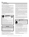
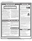
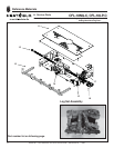
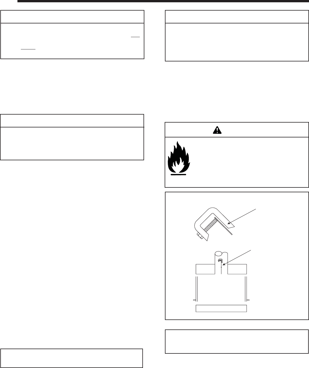
Figure 2.
DAMPER CLAMP
OPEN DAMPER
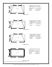
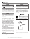
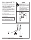
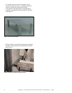
These models contain complete gas-burner, grate(s), and
log components needed. Use caution when handling logs
to avoid damage. Position the gas-burner assembly to the
rear of the fi replace. The ST-CFL-24 log set should be
positioned in the center of the unit. Once fully assembled,
the front log will extend forward of the burner assembly.
CAUTION
When installing this log set in a factory built fi replace, be
certain to consult the fi replace installation manual. ALL
knockouts in the fi replace through which the gas supply line
is run MUST be resealed with insulation after the gas line
is in place.
2
2
Getting Started
Note: The gas supply line should be purged of any trapped
air prior to the fi rst fi ring of the unit.
CAUTION
Standing Pilot units only: During the initial purging and
subsequent lightings, NEVER allow the gas control valve knob
to remain depressed in the "PILOT" position without pushing
the ignitor button at least once every second.
Fire Risk
• Open the chimney damper to its FULLY
OPEN position when burning this gas log set.
• Logs must NEVER be burned without the fl ue
damper in the FULL OPEN position. Failure
to do so is dangerous to your health and
voids all warranties.
WARNING
Note: The Commonwealth of Massachusetts requires that
the chimney fl ue damper, when used with gas logs, shall be
welded open or completely removed.
5. A damper stop clamp with set screw is provided to
prevent full closure of the fi replace damper blade. Attach
the clamp to the edge of the damper blade with pliers or
wrenches. If the damper stop supplied does not fi t the
application, use a permanent means that will keep the
damper open to a MINIMUM of 51 square inches (328cm
2
).
See Figure 2.
CAUTION
To minimize the possibility of spillage and to maximize proper
draft, position the log set as close to the back of the fi replace
as possible. The ST-CFL-24 log set should be positioned in
the center of the unit.
A. Installation
1. Run proper size gas line into fi replace. A 1/2 inch
(13mm) gas line, with a 3/8 inch (10mm) reduction for
hook-up, is usually suffi cient for the Gas Log set; how-
ever, if the run is unusually long, a larger line may be re-
quired. Contact your local gas company or Department
of Building and Safety if there are any questions.
2. Minimum inlet gas supply pressure for purposes of in-
put adjustment, shall be 7.0 inches w.c. (1.75kPa) for
natural gas and 11.0 inches w.c. (2.75kPa) for propane
(LP gas). Maximum inlet gas supply pressure shall be
14.0 in. w.c. (3.5kPa) for both natural gas and propane
(LP gas). Manifold (outlet) pressure should be 3.5
inches w.c. (.87kPa) for natural gas and 10.0 inches
w.c. (2.5kPa) for LP gas.
3. The appliance and its individual shut off valve must be
disconnected from the gas supply piping system during
any pressure testing of the system at test pressures in
excess of 1/2 psig (3.5kPa).
4. This appliance must be isolated from the gas supply
piping system by closing its individual manual shut off
valve during any pressure testing of the gas supply
piping system at test pressures equal to or less than
1/2 psig (3.5kPa).