


Heatilator • Caliber Mesh CD Series-SIT Valve • 4040-849 Rev J • 06/08 51
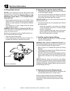
E. Electrical Service and Repair
WARNING! Risk of Shock! Label all wires prior to
disconnection when servicing controls. Wiring errors can
cause improper and dangerous operation. Verify proper
operation after servicing.
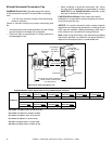
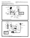
Ignitor
Flame
Sensor
Pilot Assembly
GRN
ORG
BLK
ORG
Control
Box
To
Junction
Box
Battery
Pack
3V
Adapter
BLK
BRN
RED
RED
WHT
Optional
SPST Wall Switch
or
Optional Remote
Valve
WHT
+
-
+
-
WHT
RED
GRN*
*
GRN wire only for
use with optional
wall switch
WSK-MLT
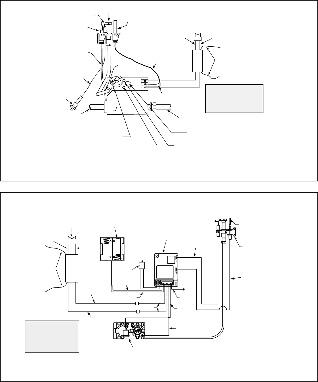
Figure 12.3 Intellifi re Pilot Ignition (IPI) Wiring Diagram
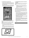
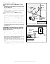
Pilot
Ignitor
To Burner
Gas Inlet
Inlet Tap
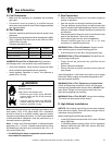
ORG
SILVER
TO
PILOT
TH
TP
TH/TP
Thermopile
WHT
RED
BRN
Manifold
(outlet)
Pressure Tap
Thermocouple
Copper
Tubing
Push
Button
Ignitor
Pilot
Adjustment
Cap
Wall Switch (or
thermostat if
heater-listed)
Manifold Pressure
Adjustment Fitting
WHT
RED
GRN*
*
GRN wire only
for use with
optional wall switch
WSK-MLT-HTL
Figure 12.2 Standing Pilot Ignition Wiring Diagram
WARNING! Risk of Shock! Replace damaged wire with
type 105° C rated wire. Wire must have high temperature
insulation.