


Heatilator • Caliber CD Series • 4040-263 Rev N • 11/0854
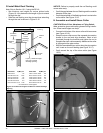
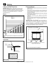
1 in. (25 mm) min.
to perpendicular wall
A
3-1/2 in. (89 mm) min.
from fireplace opening
to perpendicular wall
B
Mantel Leg or
Perpendicular Wall
Top of
Appliance
Drywall
A
B
Measured from top of hood (in inches)
3
4
5
6
7
8
9
10
11
12
13
14
15
16
5
5-1/2
6-1/4
7
7-3/4
8-1/2
9-1/4
10
10-3/4
11-1/2
12-1/4
13
13-3/4
14-1
/
13
13
Finishing
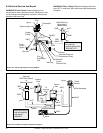
A. Mantel and Wall Projections
WARNING! Risk of Fire! Comply with all minimum clear-
ances to combustibles as specifi ed. Framing or fi nishing
material closer than the minimums listed must be construct-
ed entirely of noncombustible materials (i.e., steel studs,
concrete board, etc).
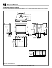
Figure 13.1 Minimum Vertical and Maximum Horizontal Dimen-
sions
Note: All
measurements
in inches.
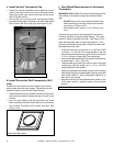
Figure 13.2 Mantel Leg or Wall Projections (Acceptable on both
sides of opening)
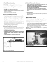
Mantels
Combustible
0 in.
0 in.
0 in.
Finish wall material may be
combustible - Top and Sides
High Temperature Sealant (300° F/149° C min.)
Top and Side Seal Joint
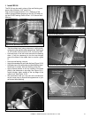
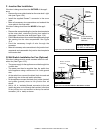
B. Facing Material
• Metal front faces may be covered with non-combustible
materials only.
• Facing and/or fi nishing materials must not interfere with
air fl ow through louvers, operation of louvers or doors,
or access for service.
• Facing and/or fi nishing materials must never overhang
into the glass opening.
• Observe all clearances when applying combustible
materials.
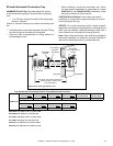
• Seal joints between the fi nished wall and appliance top
and sides using a 300 °F minimum sealant. Refer to
Figure 13.3.
WARNING! Risk of Fire! DO NOT apply combustible ma-
terials beyond the minimum clearances. Comply with all
minimum clearances to combustibles as specifi ed in this
manual. Overlapping materials could ignite and will inter-
fere with proper operation of doors and louvers.
Figure 13.3 Noncombustible Facing Diagram