


Hearth & Home Technologies • Bravo, Aztec • InD • 703-900 Rev. N • 8/06
6
3
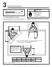
Framing and Clearances
NOTE:
• Illustrations refl ect typical installations and are FOR
DESIGN PURPOSES ONLY.
• Illustrations/diagrams are not drawn to scale.
• Actual installation may vary due to individual design
preference.
WARNING
Fire Risk
Provide adequate clearance:
• Around air openings
• To combustibles
• For service access
Locate appliance away from traffi c areas.
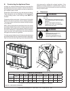
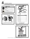
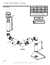
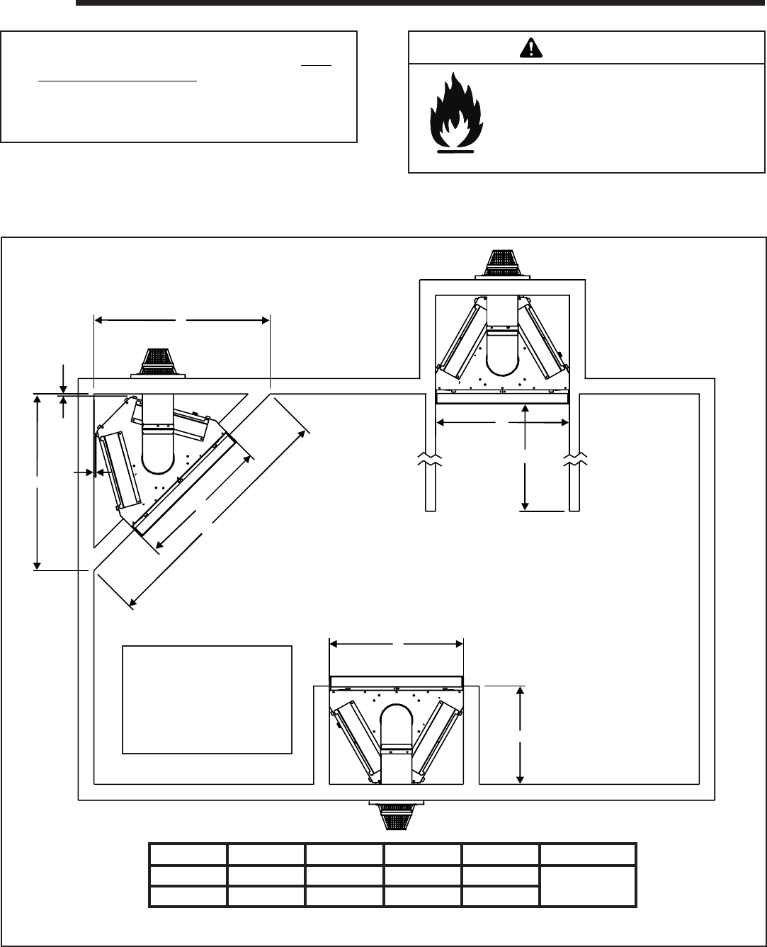
A. Selecting Appliance Location
When selecting a location for your appliance it is important to
consider the required clearances to walls (see Figure 3.1).
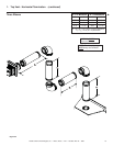
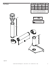
Figure 3.1 Appliance Locations
NOTE: For actual appliance dimensions refer to Sec-
tion 16.
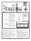
ABCD E
Inches 45-1/8 34-3/8 63-7/8 25-1/4
No maximum
Millimeters 1146 873 1622 641
A
½
½
A
B
C
B
E
B
D
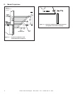
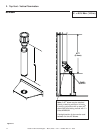
In addition to these framing dimensions, also reference the following sections:
• Clearances and Mantel Projections (Section 3.C and 3.D)
• Vent Clearances and Framing (Section 6).
NOTE:These dimensions
are for fl ush wall fi nishing
method. For a recessed
arch fi nishing method refer
to Option B in Finishing
(Section 11).