


September 1, 2008
Page 13Quadra-Fire · Topaz · 7009-113G
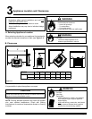
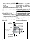
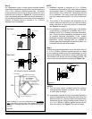
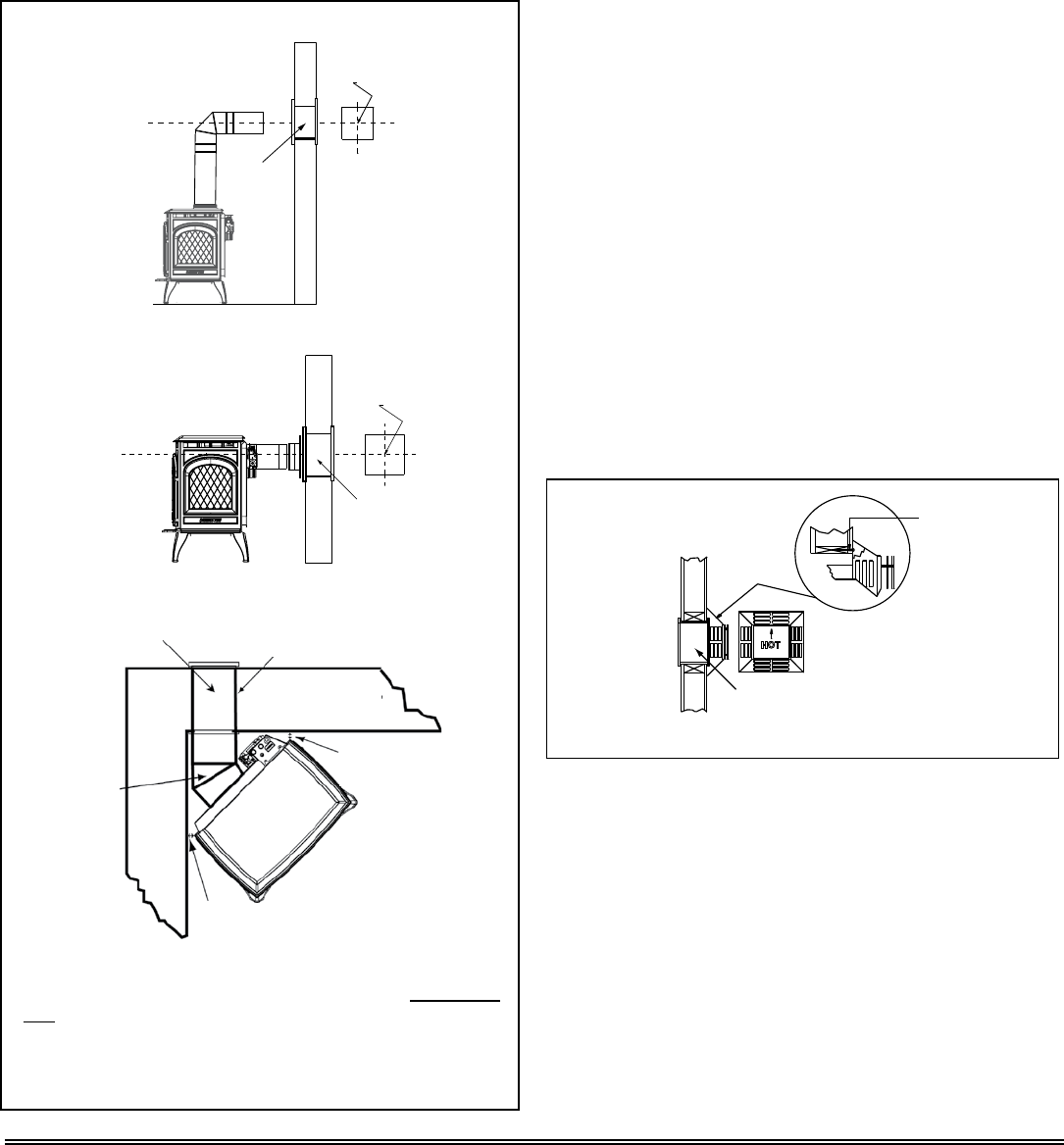
Figure 5.5
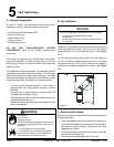
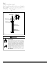
When installing in a rear vent configuration with no vertical
rise: a Snorkel Kit must be used, and a derating orifice must
be installed. The appropriate orifice is supplied with the Rear
Vent Kit.
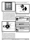
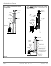
45° Elbow in Corner Installation
Center Line
Wall Thimble
Center Line
Center of Hole
Center Line
Center Line
Center of Hole
Wall Thimble
Top Vent
Rear Vent
14 in. (356mm) Pipe Length
Wall Thimble
45°
Elbow
Max. Wall Depth
10 in. (254mm)
1 in. (25mm)
clearance from
appliance corner to
1 in. (25mm) clearance from appliance
corner to combustible wall
NOTE:
(1) Installation requires a minimum of 6 in. (152mm)
horizontal run of vent with a 1/4 in. (6mm) rise run towards
the termination. Each 1 ft. (305mm) of horizontal venting
must include a 1/4 in. (6mm) rise. Never allow the vent
to run downward. This could cause high temperatures
and may present the possibility of a house or structure
fire.
(2) The location of the horizontal vent termination on an
exterior wall must meet all local and national building
codes, and must not be easily blocked or obstructed,
see Figure 4.4 on page 9.
(3) For installations requiring a vertical rise on the exterior
of the building, a snorkel kit is available with a 14 in.
(356mm) and a 36 in. (914mm) tall snorkel termination
cap. Follow the same installation procedures as used
for standard horizontal terminations. If the snorkel
termination must be installed below grade (i.e. basement
application), proper drainage must be provided to
prevent water from entering the snorkel termination. Do
not backfill around snorkel termination.
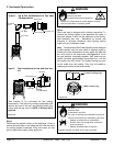
HOT
WOOD
SCREW
WALL THIMBLE
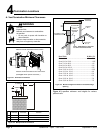
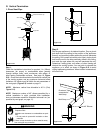
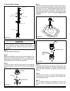
Step 4.
Position the horizontal termination cap in the center of the 10
in. x 10 in. (254mm x 254mm) square hole and run a bead
of non-hardening mastic around its outside edges, so as to
make a seal between it and the wall, attach termination cap
to the exterior wall with the four wood screws provided. The
arrow on the vent cap should be pointing up (Figure 5.6).
Figure 5.6
NOTES:
(1) The four wood screws provided should be replaced
with appropriate fasteners for stucco, brick, concrete,
or other types of sidings.
(2) A termination cap with a built-in vinyl siding standoff is
highly recommended on a building with vinyl siding. The
pilot hole will be 2 in. (51mm) closer to the bottom of the
square than the top. Using a framing square, draw a 14
in. x 14 in. (356mm x 356mm) square around the pilot
hole in the siding. See Figure 5.7 on the next page.
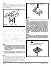
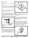
Step 3.
For installations using a round support box/wall thimble
(check pipe manufacturer's instructions), mark the wall for a
10 in. x 10 in. (254mm x 254mm) square hole. The center
of the square hole should line up with the center line of the
horizontal pipe, as shown in Figure 5.5. Cut and frame the
hole in the exterior wall where the vent will be terminated. If
the wall being penetrated is constructed of noncombustible
material, i.e. masonry block or concrete, a 7 in. (178mm)
diameter hole is acceptable.