


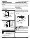
Page 24
433-1390G
September 1, 2008
R
7100FP EPA Woodburning Fireplace
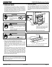
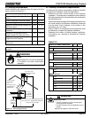
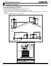
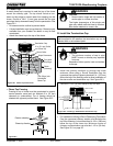
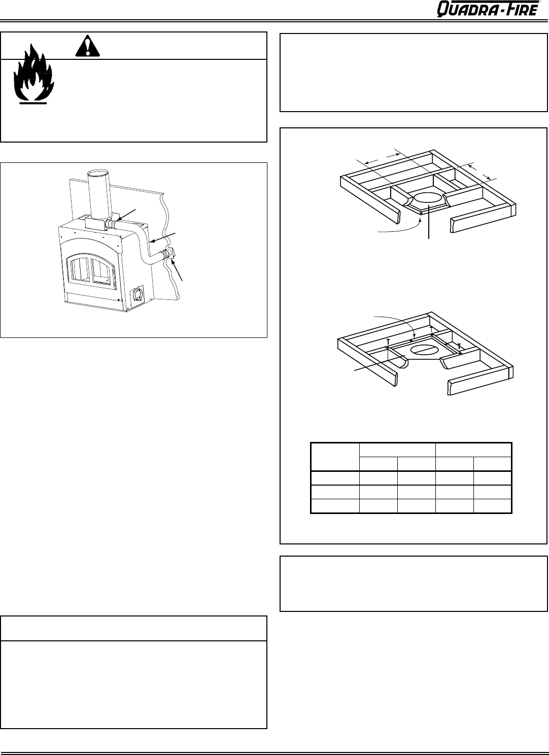
F. Install the Ceiling Firestops
• Mark and cut an opening in the ceiling for the ceiling
firestop being used. See Figure 24.2.
• Frame the opening with the same size lumber used in the
ceiling joists.
• Install the firestop spacer.
These firestop spacers are designed to provide the
minimum 2 in. (51 mm) air space required around the
chimney. In all situations, the firestop spacers are to be
nailed to the ceiling joists from the bottom or fireplace
side, EXCEPT when the space above is an insulated
ceiling or attic space. In this situation, the firestop spacer
must be nailed from the top side to prevent loose insula-
tion from falling into the required 2 in. (51 mm) air space
around the chimney.
NOTE: See Figures 25.1 and 25.2 on page 25.
Note: The ceiling firestop MUST be nailed to the bottom
of the ceiling joists EXCEPT when the space above is
uninsulated and the attic insulation shield is not being used
(see Figure 24.2). When the attic insulation shield is used
the ceiling firestop may be above or below the joist of an
insulated ceiling.
Note: You must provide support for the pipe during
construction and check to be sure inadvertent loading has
not dislodged the chimney section from the fireplace or at
any chimney joint.
• Ceiling firestops must be used at ceiling/floor.
• Chase construction requires ceiling firestops at each
floor or every 10 ft (3.05 m) of clear space.
• Use same dimensional lumber as joists.
Ceiling firestop slows spread of fire and reduces cold air
infiltration.
CAUTION
ROOM ABOVE (non-insulated ceiling)
ATTIC ABOVE (insulated ceiling)
B
A
Ceilng firestop
attached to bottom
of framing
Ceiling firestop
attached to top of
framing
When attic insulation
shield not used
Note: Use same dimensional lumber for framing
ceiling firestop and joists.
2 in. (51mm)
clearance
2 in. (51mm)
clearance
Figure 24.2 Installing the Ceiling Firestop
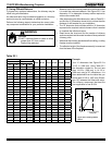
Catalog #
AB
in. mm in. mm
FS338 14-1/2 368 14-1/2 368
FS339 14-1/2 368 18-3/8 467
FS340 14-1/2 368 23 584
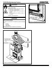
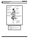
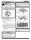
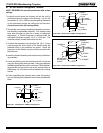
Wire Ties
Wire Ties
4" Flex
Figure 24.1 Installing Flex Pipe
Fire Risk
• The flex hose must never be
compressed or deformed!
Restricting the airflow inside the flex pipe
may increase flue pipe temperatures causing
a chase fire.
WARNING