


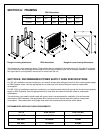

SECTION A: FRAMING
EBU Dimensions
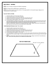
Rough-in framing dimensions EBU dimensions Rough-in corner framing dimensions
This fireplace is a zero clearance design. Combustibles may be installed to the edge of the unit. A drywall lip at the top
of the unit and four nailing flanges on the sides of the unit are provided on each unit to facilitate installation. Insulation
and vapor barrier can be placed a minimum of 2 inches from the unit.
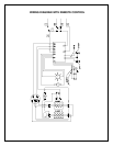
SECTION B: RECOMMENDED POWER SUPPLY WIRE SPECIFICATIONS
For 120 volt installations use two conductors, non-metallic sheath cable with ground wire for the incoming power supply
on EBU fireplace inserts. Use the appropriate wire to meet local and national electrical codes for rated power
consumption.
For 208 / 240 volt installations use three conductors, non-metallic sheath cable with ground wire for the incoming power
supply on EBU fireplaces. Use the appropriate wire to meet local and national electrical codes for rated power
consumption.
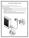
Two conductors, non-metallic sheath cable with ground wire is recommended for installation of a wall mounted
thermostat on EBU fireplaces. Use appropriate wire to meet local and national electrical codes for rated power
consumption. Thermostat switch wire gauge must match the recommended wire sizes shown below.
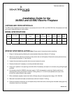
RECOMMENDED WIRE AND FUSING REQUIREMENTS
VOLTS WIRE GAUGE FUSE RATING
120 VOLT 12 GAUGE 20 AMP
208 VOLT 14 GAUGE 15 AMP
240 VOLT 12 GAUGE 20 AMP
MODEL A B C D E F
36-EBU 35.5” 38.7” 54.0” 38.0” 38.0” 40.0”
42-EBU 41.5” 44.7” 60.0” 42.0” 42.0” 46.0”