


7
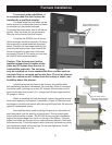
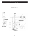
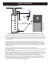
SF2600.
ThisgurerepresentsthemodelSF2600furnace.It’sintentionisto
represent the approximate location of the various controls. This draw-
ing may also be used as a reference for wiring and control spacing.
Pleasenotethatthisdrawingisforreferenceonly.Specicinstalla-
tions will vary.
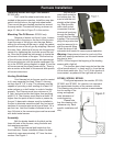
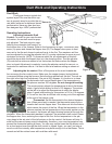
Mounting The Blower And Filter Box
Positionthelterboxbetweenthebracketsontherearofthefur-
nace,withthebottomoftheboxrestingontheangeatthebottomof
the furnace. Insert the mounting clips into the bracket slots to secure
thelterbox.(seeFigure2)Next,installtheblowerbracketsontothe
blower being sure to install the rubber feet into the brackets. NOTE:
OntheSF3500,installtheblowermountandblowerbeforethelter
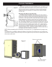
box. All hardware, brackets, etc. for the blower, will be found in the car-
tonwiththeblower.Next,positiontheblowerinthelterbox,centered
behind the inlet hole and allow approximately 1/8 in. space between
therearofthefurnaceandthebloweroutlet.Now,installthelterrail
ontothelterbox.NOTE:Thelterrailisbestinstalledontheside
toward the shaker handle, so that any pipes from the hot water coil do
notinterferewithlterinstallationorremoval.
NOTE: Before proceeding with the installation of the access door, it is suggested that the wiring be com-
pleted.
Theaccessdoorisinstalledbyslippingtheangeonthebottomoftheaccessdooroverthebottomrail
ofthelterboxopening,thenpushthetopofthedooragainstthetopofthelterboxopeningandsecure
with a sheet metal screw.
Furnace Installation
Figure 2
Filter box mounting clips
1/8 in. space between
blower and furnace