


5
Installation
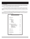
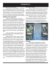
Getting Started
Thesheetmetalsidesandtopareeasily
removedtoreducethechanceofdentsand/or
scratchesinthenish.Simplyliftthetopoff,and
thatwillallowthesidestobepulledawayandup,
forremoval.Tore-install,slidethechannel,atthe
bottomofeachsidepiece,overthelipatthebot-
tomoftheboiler,andholddownwardwhilemov-
ing the side panel into place. Then slide the top
downoverthesides.
NOTE:Thesheetmetaltopholdsthesidesin
place,thus,noboltsorscrewsareneeded.
Caution: Boiler should not Be
installed Closer than 36 inChes
(915 mm) to any ComBustiBle ma-
terial
Locating Boiler
Placetheboilerasclosetothechimneyas
possible,whilestillmaintainingtheabovemen-
tionedclearances.Bolttheshakerhandleonto
theblockonthesideoftheboiler,usingthe(2)
5/16X3/4in.boltsandlock-washers.
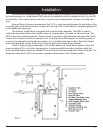
Assembly
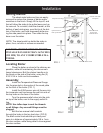
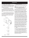
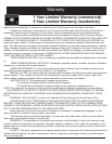
InstalltheTemperature/PressureGauge
intothepipestubinthecenteroftheroundplate
onthefrontoftheboiler(FIG.1)
InstalltheA350sensorwireallthewayinto
theimmersionwellandscrewthewellintooneof
thetopholesonthefaceoftheboiler.
Turnthepressurereliefvalveintothestub
ontopoftheboiler,nexttothesupplyoutlett-
ting.
NOTE: Use teon tape to seal the threads
on all ttings. Any unused ttings must be
plugged.
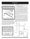
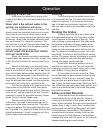
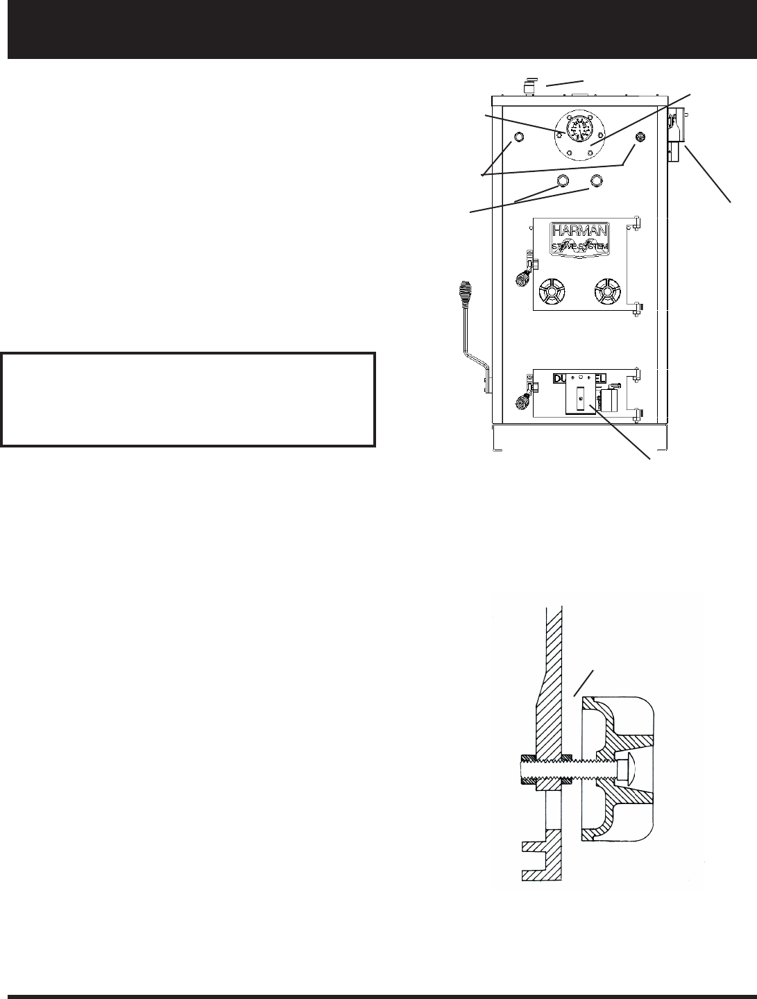
Boltthetwomanualdraftcontrols
through the holes in the top load door. (FIG.2)
Thedraftcontrolknobshouldspinfreelyand
opentoadistanceofapproximately3/8in.from
thedoorsurface,whilebeingabletocloseagainst
the door surface.
FIG.2
3/8 to 1/2 in.
Immersion Well
Temp/Pressure Gauge
Optional Electric
Back-up Elements
Automatic Draft Control
Pressure Relief Valve
FIG.1
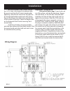
Johnson Controls
Aquastat and
Terminal Block
Shaker Handle
Domestic Hot Water
Coil Option