


SKU 98904 For technical questions, please call 1-800-444-3353 Page 5
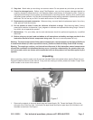
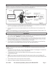
Air Connections
Caution: To avoid injury, make certain that the air compressor is unplugged from the power source and that all
pressure is released from its tank before connecting the Air Filter/Regulator to it.
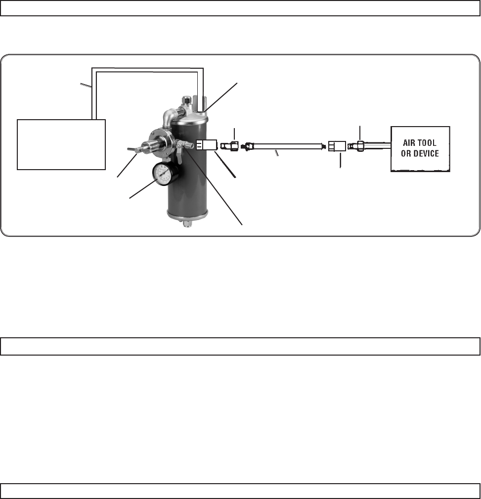
Figure 6
Air Inlet
Air Hose
(5B)
Air Hose
Pressure Gauge (6B)
Regulator Handle (1C)
AIR COMPRESSOR
1. Connect an air hose (not included) or pipe (not included) beween your air compressor (not included) and
the 1/2” air inlet located on top of the Filter Cap (2A). See Figure 6.
Connect another air hose (not included) between the Air Valve (5B) and your air tool or paint gun. See 2.
Figure 6.
NOTE: It is recommended that you use male and female quick connectors as shown in Figure 6 above. This
will allow you to quickly change air tools and hoses if requied.
Operation
Turn on the air compressor and check for leaks. If any are found, turn the Compressor off, drain air from 1.
tank, and x the leak. WARNING: Do not exceed 160 PSI during use.
With the compressor ON, turn the Regulator Handle(1C) to set the pressure that you want. Look at the 2.
Pressure Gauge (6B) while you turn the Adjusting Screw. Stop turning the Regulator Handle (1C) when
the Pressure Gauge needle points to the desired pressure. See Figure 6.
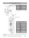
You must drain the Air Filter/Regulator of water daily. With the unit under pressure, turn the Drain Plug 3.
(14A) to expel any accumulated moisture from the Air Filter. See page 6 parts list A.
Maintenance
Caution: To avoid injury, make certain that the Air Filter/Regulator is depressurized before performing any
maintenance on it.
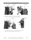
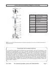
Periodically remove the Filter (6A), rinse it out with water and replace. If it is damaged or if it needs to be 1.
replaced you can order a new one by calling 1-800-444-3353
To disassemble the air lter; remove the Nipple (1B) from the Housing (7A) by twisting it in a 2.
counterclockwise rotation.
NOTE:3. You will need to rmly hold the Cap Nut (13A), with a wrench, while you turn the Nipple (1B)
because they are both connected to the same Stud (10A). See the parts list and assembly diagram page
6.
Once the Nipple (1B0 is removed the lter will be accessible.4.
Make sure to tighten the Nipple (1B) before pressurizing the unit.5.
Male Quick Coupler
(not supplied)
Male Quick Coupler
(not supplied)
Female Quick Coupler
(not supplied)
Female Quick Coupler
(not supplied)
Air Valve (5B)