SKU 01318 For technical questions, please call 1-800-444-3353. Page 2
SPECIFICATIONS
Handle 7”
Inlet Pipe Diameter 1-1/4” NPT
Maximum Lift 25 Feet
Maximum Volume 12 oz. Per Stroke
Assembled Dim. 17” H x 8” W
Spout to Handle 12-1/2”
Construction Cast Iron Body, Base, and Handle
Aluminum Internal Parts
This product can be set up to pump water but
never use this product to pump drinking (potable)
water.
WARNING!
Wear ANSI-approved safety goggles during 1.
assembly.
Use for pumping water only. 2.
WARNING:3. This product contains or, when
used, produces a chemical known to the State
of California to cause cancer and birth defects
or other reproductive harm. (California Health
& Safety Code § 25249.5, et seq.)
ASSEMBLY
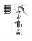
Place the 1. Base (13) on a flat, smooth
surface.
Set the 2. Valve Assembly (12) in the circle
groove of the Base (13). It will only t with the
metal plate up.
Put the 3. Cylinder (9) on the Valve Assembly
(12). Line up the Cylinder (9) so that the bolt
holders on each side of sit over the two drilled
openings on the Base (13). The spout on the
Cylinder (9) should rest over the at side of
the Base (13).
Slip a 4. Bolt (10) and a Washer (11) into the
bolt holder on the Cylinder (9). Put a Nut (14)
under the Base (13) and screw it onto the Bolt
(10). Hand tighten. Repeat the procedure
on the other side. Then, wrench tighten both
Bolts (10).
Set the 5. Piston Assembly (8) with the screw
eyelet up, down into the Cylinder (9).
Put the 6. Cover (5) onto the Cylinder (9) so the
screw eyelet on the Piston Assembly (8) ts
through the opening in the center of the Cover
(5). The large bolt hole on the Cover (5) should
sit opposite the spout on the Cylinder (9). The
two recessed Screw Bolts (4) should straddle
each side of the spout on the Cylinder (9).
Tighten the recessed Screw Bolts (4) with a
small at screwdriver. With a crescent wrench,
tighten the large Bolt (6) on the Cover (5)
opposite the spout.
Attach the 7. Handle (2) to the Piston Assembly
(8) using a Bolt (3) and Nut (1). Make sure
the hole on the Handle (2) that attaches to the
Cover (5) rests between the bolt housing on the
Cover (5). If necessary, rotate the screw eyelet
on the Piston Assembly (8) to nd the best
t. Tighten the Nut (1). Next, run the Bolt (7)
through the bolt housing on the Cover (5) and
the Handle (2) and tighten the Nut (1).
Attach 1-1/4” NPT threaded water source 8.
pipe to the threaded inlet on the bottom of the
pump.
Secure the pump by screwing the base to a 9.
stable surface.
OPERATION
This pump needs to be primed before every 1.
use. Keep a pitcher (not included) of water near
the pump for this purpose. Pump the handle
up and down while pouring about a quart of
water into the top of the pump to prime it and
start the water ow.
Note: DO NOT STOP PUMPING THE HANDLE
UNTIL FINISHED! Stopping, even momentarily,
will cause the pump to lose its prime and no
longer work until primed again.
Rell the pitcher. Then, continue pumping as 2.
needed.
Note: Do not pump drinking water from this
pump.
REV 02d; 09b