15 20 25 30 30
Rated Load Amps 5.4 8.0 10.1 11.8 13.2
Compressor Locked Running
Amps 36.0 53.5 61.0 78.0 78.0
Full Load Amps 0.86 0.86 1.4 1.6 1.6
Fan Motor Rated HP 1/8 1/8 1/4 1/3 1/3
Nominal RPM 1000 1000 1075 1120 1120
Liquid Line OD - In (mm) 3/8"[9.52] 3/8"[9.52] 3/8"[9.52] 3/8"[9.52] 3/8" [9.52]
Vapor Line OD - In (mm) 3/4"[19.05] 3/4"[19.05] 3/4"[19.05] 7/8"[22.2] 7/8"[22.2]
R-22 Charge -Oz (g) 84.81[2400] 84.81[2400] 123.67[3500] 137.81[3900] 141.34[4000]
Net Dimensions - In (mm) 21 1/2"*21 1/2"*23 3/8" 21 1/2"*21 1/2"*26 7/8" 24 1/4"*24 1/4"*23 3/8" 241/4"*24 1/4"*26 7/8" 24 1/4"*24 1/4"*30 3/8"
W*D*H
[547* 547*595]
[547* 547*683]
[616* 616*595]
[616 *616*683] [616 *616*771]
Shipping Dimensions - In (mm) 23" *23" *25 " 23"*23"*28 1/2" 26 7/8"*26 7/8"*25" 26 7/8"*26 7/8"*28 1/2" 26 7/8"*26 7/8"*32"
W*D*H
[585* 585*637]
[585* 585*725]
[
682* 682*637]
[682*682*725] [682*682*813]
Net Weight - Lbs (kg) 143[65] 150[68] 176[80] 187[85] 198[90]
Approx Shipping Weight - Lbs (kg) 158[72] 165[75] 192[87] 202[92] 214[97]
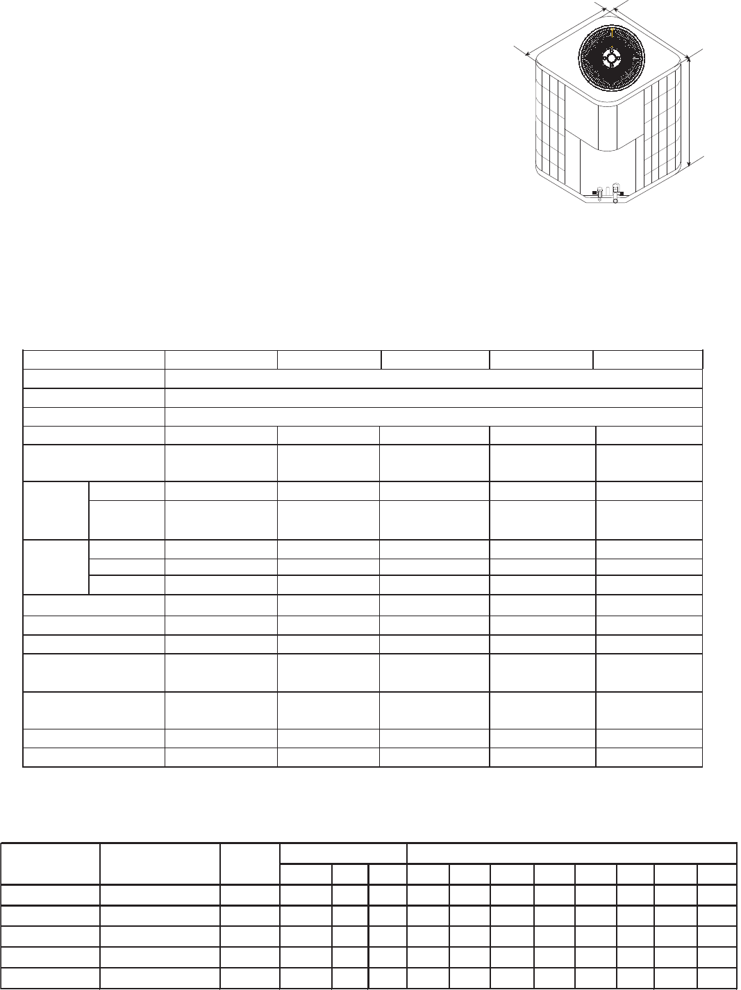
The dimensions for the condensing unit are illustrated in Figure 1. Physical and electrical
specifications are provided in Table 1 for 13 SEER systems respectively.
Model:HC18-42D2VAR
Figure 1
2
Table 2:System Cooling Capacity
Table 1:
MODEL: HC18D2VAR HC24D2VAR HC30D2VAR HC36D2VAR HC42D2VAR
Unit Supply Voltage
Normal Voltage Range
Compressor Brand
Minimum Circuit Amps
208/230 60Hz 1PH
197 - 253
Bristol
7.6 10.9 14.0
16.4
18.1
Max Fuse or Max CKT. BKR.
(HACR per NEC )
H
W
D
3.SPECIFICATION
Cooling
Capac ity SEE R CFM
80 85 90 95 10 0 10 5 11 0 11 5
HC18 D2VAR HB 2400 VD 1M 20 M
1700 0 13 67 0 1921 0 1864 9 1802 0 1700 0 1674 5 1649 0 1623 5 1598 0
HC24 D2VAR HB 2400 VD 1M 20 H
2300 0 13 90 0 2599 0 2523 1 2438 0 2300 0 2265 5 2231 0 2196 5 2162 0
HC30 D2VAR HB 3600 VD 1M 22 L
2900 0 13 112 5 3277 0 3181 3 3074 0 2900 0 2856 5 2813 0 2769 5 2726 0
HC36 D2VAR HB 3600 VD 1M 22 H
3500 0 13 124 0 3955 0 3839 5 3710 0 3500 0 3447 5 3395 0 3342 5 3290 0
HC42 D2VAR HB 4800 VD 1M 22 L
4100 0 13 148 0 4633 0 4497 7 4346 0 4100 0 4038 5 3977 0 3915 5 3854 0
ARI data of indoo r
Outdoo r
Indoo r
Coo ling Capacity with different outdoo r temperature
Indoorfan
spee d
The Figure 2 show a schematic of the cooling only system.


