


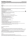
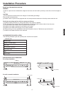
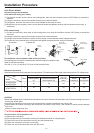


ELECTRICAL WIRING
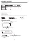
(1) Cut the wire end with a wire cutter or wire-cutting pliers, then strip the insulation to about 15/16"(25mm) to expose the
solid wire.
(2) Using a screwdriver, remove the terminal screw(s) on the terminal board.
(3) Using pliers, bend the solid wire to form a loop suitable for the terminal screw.
(4) Shape the loop wire properly, place it on the terminal board and tighthen securely with the terminal screw using a
screwdriver.
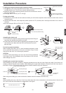
B.For strand wiring
(1) Cut the wire end with a wire cutter or wire-cutting pliers, then strip the insulation to about 3/8"(10mm) to expose the
solid wire.
(2) Using a screwdriver, remove the terminal screw(s) on the terminal board.
(3) Using a round terminal fastener or pliers, securely clamp a round terminal to each stripped wire end.
(4) Position the round terminal wire, and replace and tighten the terminal screw using a screwdriver.
A.For solid core wiring (or F-cable)
Screw with
special washer
Round
terminal
Wire
Terminal
board
Screw with
special washer
Round
terminal
Wire
A. Solid wire
Insulation
Loop
Strip 15/16"(25mm)
B. Strand wire
Round
terminal
Strip 3/8"(10mm)
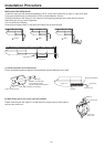
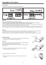
After passing the connection cord and power cable through the insulation tube,
fasten it with the cord clamp.
Use VW-1, 0.5 to 1.0 mm thick, PVC tube as the insulation tube.
Fix connection cord and power cable at the cord clamp
Insulation tube
Cord clamp
21
Installation Procedure
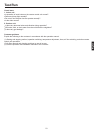
CAUTION
Match the terminal block numbers and connection cord colors with those of the outdoor unit. Erroneous wiring may cause
burning the electric parts.
Connect the connection cords firmly to the terminal block. Imperfect installation may cause a fire.
Always fasten the outside covering of the connection cord with the cord clamp. If the insulator is chafed, electric leakage
may occur.
Always connect the ground wire.
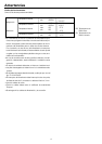
Electrical requirement
Connect wiring to the terminals
(1) Remove the cord clamp.
(2) Process the end of the connection cords to the dimensions shown in wiring diagram.
(3) Connect the end of the connection cord fully into the terminal block.
(4) Fasten the connection cord with a cord clamp.
(5) Fasten the end of the connection cord with the screw.
Connect indoor unit and outdoor unit
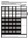
Select wire sizes and circuit protection from table below. (This table shows 20m length wires with less than 2% voltage drop).
30
Item
Model
Phase
Switch breaker
(A)
Circuit breaker
Overcurrent protector
rated capacity (A)
Power source
wire size
(minimum)
(mm
2
)
140
30 6.0
Switch
breaker(A)
Earth leakage breaker
Leak
current(mA)
40
AC28ES1ERA
AC36ES1ERA
1 30 4.0 1020 30
AC48FS1ERA
AC60FS1ERA