


27
(1)
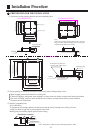
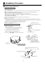
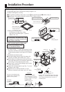
3. Install ornament panel on indoor unit.
As shown in Fig . 7, match the position of swing
flap motor with that of the indoor unit piping hole ,
so that ormament panel can be placed on to indoor
unit.
Installation of ornament panel
Place the holding ring on swing flao motor side
teporarily on hooks of the indoor unit. (2 pcs)
Put the other two holding rings on the hooks at
both
side of the indoor unit. (Care should be taken not to
push wiring of swing flap motor into seals).
Screw in all 4 screws under holding ring for about
15mm. (Pancl will rise).
Adjust the ornament panel as per Fig. 7 to cover
opening on the ceiling.
Tighten screws to redrce the thickness of seals
between ornament and indoor unit to 5-8mm.
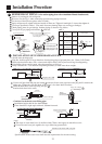
If indoor unit is at horizontal level and water
drainage is smooth, then, indoor unit height
can be adjusted throrgh holes at corners of
ornament panel.
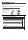
If screws are not tighten tight,
problems in Fig, 8 might occur.
Tighten screws properly.
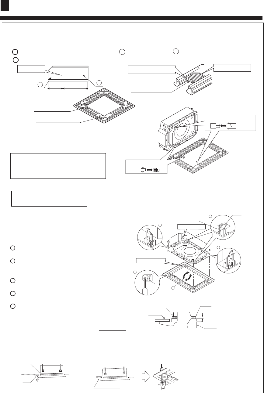
If there are still space
after tightening of screws,
please readjust the height
of indoor unit.
(Refer to Fig. 9)
Leave no space.
Fig. 9
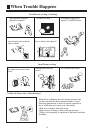
Gas leakage.
Gas leakage
from roof.
Contamination
Mist exists and drop down.
Fig. 8
For indoor unit installation, please
refer to Installation Manual.
(2)
1
2
3
4
5
5
_
8mm
3
2
2
1
4
Holding ring
Piping hole position
Swing flap motor
Fig. 7
Seal
Indoor unit
Ceiling material
Ornament panel
Hook
Caution
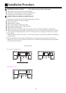
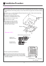
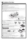
2. Mounting on high ceiling
(1) Ornament panel can be mounted on ceiling as high as 3 m.
(2) Please install pad as accessary.
Cut open the pad along cutting ling. Use part a only and discard part b . (Refer to Fig. 4)
Install part a of the pad on the place shown in Fig. 5. Refer to Fig. 6.
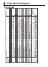
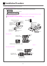
(3)Wiring on ornament panel
Connecting of wiring of the swing
flap motor on ornament panel. (2 places)
(Refer to Fit . 10)
If connecting is not made, error code
(A7) appears on remote controller. So,
make proper connecting.
Side of ornament panel
Fig. 10
Wiring diagram
Side of indoor unit
Fig. 4
50
Cutting line
100
a
b
Place it on the frame.
Part a of the pad
Leave no space.
Fig. 6
Part a of the pad
Swing flap motor
Fig. 5
1
2
Installation Procedure