


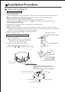
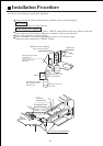
Wire connection for built-in indoor unit
Insert from outside the connection wire and signal transmission wire through the wall hole
with pipeline already arranged.
Pull out the front ends of connection wire and signal wire and make a circle on the signal wire.
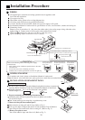
Connect the connection wire according to the connection method and indoor and outdoor wiring
diagram.
Pull the connecting conductor outwards slightly to confirm it is clamped tightly.
Connect the plug for connecting the signal wire with the plug of the signal wire connected
from the indoor unit.
After wire connection is finished, install wire clips using the same method for connection wire
clamping.
Note: When connecting the indoor unit and the outdoor unit, please do connect the wires
with the same color terminals.
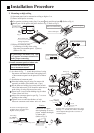
Notes:
Before connecting the conductors between indoor unit and outdoor unit, check for the
number on the indoor and outdoor units connecting terminals. Connect the terminals with
the same color and number with a wire.
Wrong connection would damage the controller of the air conditioner or the machine
couldnt operate.
Do not connect the connection wire and signal wire with the same cable. They shall be
connected respectively to ensure system normal operation.
For some models, connection wire shall be provided by the user.
If the fuse on PC board is broken please change it with the type of T 3.15A /250VAC.
The power cable and connecting cable are self-provided.
All the cables shall have got the European authentication certificate.
The breaker of the air conditioner should be all-pole switch; and the distance between
its two contacts should be no less 3mm. Such means for disconnection must be
incorporation in the fixed wiring.
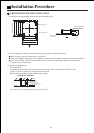
The signal wire must be shielded wire.
H05RN-F 3G (1.0~1.5)mm
2
power cable
Signal cable
H05RN-F 2x(0.75~1.5)mm
2
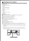
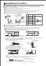
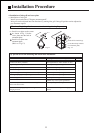
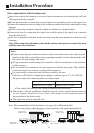
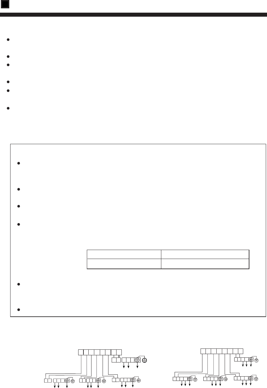
Note: The terminal block will be the below two types due to different models.
When wiring, please select the proper wiring type due to the actual terminal block.
P Q
Y/G
L N
PQ LN
P Q
L N
Y/G
P Q
L N
Y/G
INDOOR UNIT
TERMINAL BLOCK
P Q P Q P Q P Q
A1 A2 B1 B2
OUTDOOR UNIT
TERMINAL BLOCK
1PH,220-230V~,50Hz
POWER SUPPLY:
Y/G
1PH,220-230V~,50Hz
POWER SUPPLY:
1PH,220-230V~,50Hz
POWER
SUPPLY:
1PH,220-230V~,50Hz
POWER
SUPPLY:
Y/G
1PH,220-230V~,50Hz
POWER SUPPLY:
P Q L N
Y/G
1PH,220-230V~,50Hz
POWER SUPPLY:
Y/G
1PH,220-230V~,50Hz
POWER SUPPLY:
Y/G
1PH,220-230V~,50Hz
POWER SUPPLY:
P Q L N
P Q L N
P Q L N
INDOOR UNIT
TERMINAL BLOCK
P Q P Q P Q P Q
A1 A2 B1 B2
OUTDOOR UNIT
TERMINAL BLOCK
Installation Procedure
24