


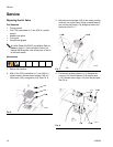
Service
22 310622L
.
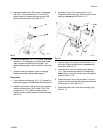
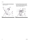
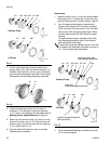
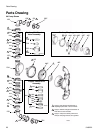
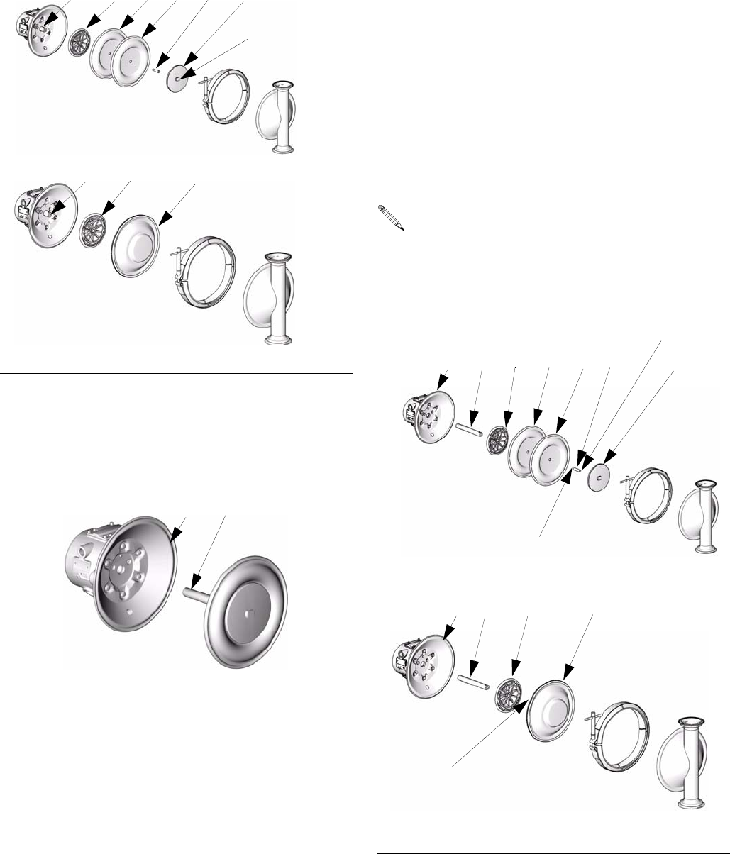
7. Pull the other diaphragm assembly and the dia-
phragm shaft (121) out of the center housing (101).
Hold the shaft flats with a 19 mm open end wrench,
and remove the diaphragm assembly from the shaft.
Disassemble the remaining diaphragm assembly.
8. Inspect the diaphragm shaft (121) for wear or
scratches. If it is damaged, inspect the bearings
(117) in place. If the bearings are damaged, refer to
Bearing and Air Gasket Removal on page 23.
9. Reach into the center housing (101) with an o-ring
pick and hook the u-cups (110), then pull them out
of the housing. This can be done with the bearings
(117) in place. See F
IG. 22.
10. Clean all parts and inspect for wear or damage.
Replace parts as needed.
Reassembly
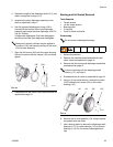
1. Install the shaft u-cups (110) so the lips face out of
the housing (101). Lubricate the u-cups. See reas-
sembly of bearing and air gasket removal, page 24.
2. Non 3A approved diaphragms: Assemble dia-
phragm (446), backer (447) if present, and plate
(445) onto plate (444) with screw (143). Rounded
side of plate (445) should face diaphragm. Make
sure the side marked AIR SIDE faces the center
housing.
3A approved diaphragms: Assemble plate (445)
onto diaphragm assembly (446). Round side of
plate should face diaphragm.
3. Screw assembled diaphragm assembly into shaft
(121) and hand tighten.
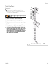
F
IG. 17
F
IG. 18
TI8772a
121
445
3A Pump
TI8773a
446*
444
445
121
Y
143
446*
447
Sanitary Pump
TI4789a
121
101
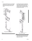
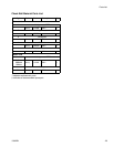
Thread locker must be applied to screw (143) and
to threads of 3A diaphragm assembly as shown in
F
IG. 19 for all diaphragm assemblies.
F
IG. 19
446*
444
445121101
TI8775a
3A Pump
Sanitary Pump
446*
445
121101
143
shaft side:
medium strength thread lock
diaphragm plate side:
high strength thread lock
TI8774a
medium strength thread lock
(bolt not shown)
447