– 9 –
Burning Equipment (NFPA 31)” (as applicable), local
codes and the manufacturer’s instructions. The burner
should be installed only by a qualified Oil-Burner Technician.
Oil Supply Connections
All aspects of oil tank location and installation, tank size, oil
piping supply and burners, including any fittings, valves, fil-
ters or any fuel handling components must comply with:
• “Installation Code for Oil Burning Equipment
(CAN/CSA-B139)”, (Canada).
• “Standard for the Installation of Oil-Burning
Equipment. (NFPA 31)”, (USA).
• Local codes and regulations.
• Information provided with burner and fuel pump.
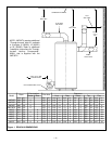
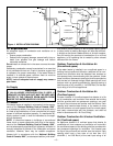
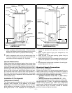
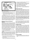
Install the oil supply tank with fill and vent lines of adequate
capacity as shown in Figure 4. When an appliance using a
float valve between the supply tank and the burner is con-
nected to a supply tank over 9 Canadian gallons capacity, a
valve operated by a fusible link, shall be installed in the fuel
line adjacent to, and upstream from, the float valve. If any
part of fuel oil tank is above level of burner, an anti-siphon
device must be used to prevent flow of oil in case of oil line
break. Support the oil lines as required by applicable codes.
Make tank connections with swing joints or copper tubing to
prevent breaking in case the tank settles. Make the swing
joints so they will tighten as tank settles. Non-hardening pipe
joint compounds should be used on all threads. Do not use
Teflon
®
tape as an oil pipe sealant. It can cause valves to
fail creating hazards. Do not use compression fittings.
Underground pipe must be run in a casing to prevent oil
leaking into ground or under floor. Check local codes for
more information.
Water Supply Connections
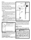
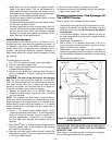
Pipes and fittings should be installed in as shown in the
installation drawing (Figures 7 & 8). Install a shut-off valve in
the cold water supply line in close proximity to the cold inlet
of the water heater. This valve is for use only when servic-
ing the heater and must be kept open during the heater’s
operation. The water connection fittings (nipples) may con-
tain a non-metallic lining to minimize corrosion and some
models include non-metallic heat traps. These appear like
pink or blue coloured plugs in the fitting. Do not attempt to
pry these plugs loose or damage them. DO NOT APPLY
HEAT DIRECTLY TO THE WATER HEATER NIPPLES. If
copper piping is used, solder a piece of tubing to a threaded
adaptor before screwing the adaptor to the nipples. Use only
solder approved for use with potable water systems. Use a
good grade of pipe joint compound, certified for use with
potable water, on the threaded fittings. Be sure all fittings are
drawn up tight.
NOTE: Rear and Combination flue heaters are equipped
with a combination cold water inlet/drain valve.
Temperature and Pressure (T&P) Relief Valve
To reduce the risk of excessive pressures and temperatures
in this water heater, install temperature and pressure pro-
tective equipment as required by local codes. It should be no
less than a combination Temperature and Pressure (T&P)
Relief Valve certified by a nationally recognized testing lab-
oratory that maintains periodic inspection of production of
listed equipment or materials, as meeting the requirements
of the latest edition of ANSI Z21.22: Requirements for
Relief Valves and Automatic Gas Shut-off Devices for
Hot Water Supply Systems. This valve must be marked
with a maximum set pressure not to exceed the marked
MAXIMUM working pressure of the water heater (150 psi
(1034 kPa). The function of the temperature and pressure
relief valve is to discharge water in quantities, should cir-
cumstances demand. To prevent property damage, bodily
injury or hazard to life the relief valve must be allowed to dis-
charge water in the event of excessive temperature or pres-
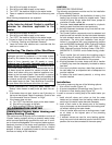
sure developing in the water heater. If the discharge tube is
not directed to a drain as shown in Figures 7 & 8 or by other
suitable means, the resulting water flow may cause sub-
stantial property damage. Install the T&P valve into the
opening provided and marked for this purpose in the water
heater, and orient it or provide tubing so that any discharge
from the cannot contact any live electrical part. Do not con-
nect discharge directly to a drain.
the discharge line:
• must not be smaller than the outlet pipe size of the
relief valve,
• opening must not be threaded, blocked, plugged,
capped, reduced in size or restricted in any manner
under any circumstances,
• must be made of material capable of withstanding
100°C (212°F) without distortion,
• must be installed so as to allow complete drainage of
both the temperature and pressure relief valve and dis-
charge line,
• must terminate near a floor drain or other suitable loca-
tion not subject to blocking or freezing, and
• must exit only within 150mm (6 in.) above, or at any dis-
tance below the structural floor.
NOTE: Rear and Combination flue units must be fitted with
a T&P Relief Valve WATTS type 40XL-5 or equivalent.
Failure to install and maintain a new, properly listed
temperature and pressure relief valve will release the
manufacturer from any claims which may result from
excessive temperature or water pressure.
Closed Water Systems
During the heating cycle of the water heater the water
expands creating a pressure build-up in the water system.
The water supply meter may contain a check valve or back
flow preventer. This will create a closed water system. A
Temperature and Pressure (T&P) Relief Valve (150 psi
(1034 kPa) maximum pressure setting, must be installed in
the system (see “Temperature and Pressure (T&P) Relief
Valve” section). To prevent the T&P valve from discharging
hot water, the loss of energy and reduce the possible build-


