


– 10 –
up of lime in the T&P valve, there are two recommendations:
1. Install a pressure relief (only) valve in the cold water
supply line. Make sure that the discharge of this valve is
directed to a drain and it is protected from freezing.
or:
2. Install an expansion tank on the cold water supply line.
For every 50 gallons of stored water, the expansion tank
must have a minimum capacity of 1.5 gallons.
Vacuum Relief Valves
Water heaters shall be protected against loss of water from
siphoning due to loss of supply pressure by a vacuum relief
valve installed in the cold water supply line at a level above
the top of the water heater. Where heating equipment has a
bottom supply, the cold water supply piping shall be carried
above the top of the heater before being routed to the sup-
ply connection and have a vacuum relief valve installed in it
at a level above the top of the storage tank. The vacuum
relief valve shall be in compliance with the standard ANSI
Z21.22 (latest issue).
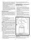
Installation Of The Aquastat
(Temperature Control)
This heater operates automatically under the control of the
aquastat, which responds to the demand of hot water.
Depending on the model, the aquastat, well and wiring is
either installed on the heater, or included in the carton con-
taining the burner. If the installation of the aquastat is
required, proceed as follows:
1. Locate the aquastat well opening in the front of the
heater.
2. Apply a good grade of pipe joint compound to the
threads on the well.
3. Install the well in the tank opening, tighten firmly to
ensure there are no leaks.
4. Insert the sensing bulb of the aquastat into the well and
secure the aquastat to the well using the screw provid-
ed.
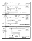
5. Wire the control to the burner as shown in the wiring dia-
grams (Figures 9, 10 & 11).
Electrical Supply Connections
General wiring requirements:
Electric shock hazard. Can cause severe personal injury or
death if power source, including service switch on heater, is
not disconnected before installing or servicing. Installations
must comply with the latest edition these codes:
• “Canadian Electrical Code Part 1 (CSA C22.1)”
(Canada).
• “National Electrical Code, ANSI/NFPA 70”, (USA).
• Any additional local, provincial, national or state codes.
Wiring must be N.E.C. Class 1. If original wire supplied with
heater must be replaced, type 105°C wire or equivalent
must be used. Supply wiring to heater and additional control
wiring must be 14 ga. or heavier. Provide an electrical
ground at heater as required by codes.
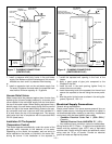
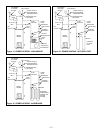
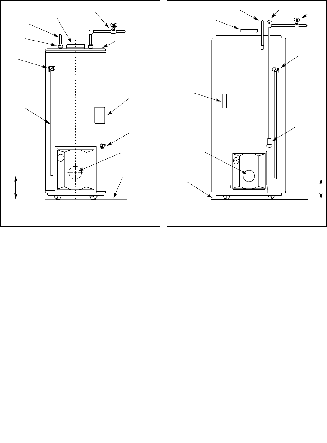
COLD WATER
SHUT-OFF
AQUASTAT
TEMPERATURE
CONTROL
T&P VALVE
COLD INLET AND
DRAIN VALVE
COMBINATION
HOT WATER
OUTLET
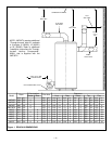
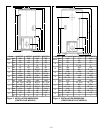
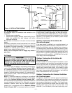
Figure 8 PLUMBING CONNECTIONS
(CENTER/REAR FLUE)
150 TO
305mm
6 TO 12”
FLUE COLLAR
CAPPED FOR REAR
FLUE USE (OPTIONAL)
VACUUM BREAKER
CENTER OF
BLAST TUBE
NON-COMBUSTIBLE
FLOOR
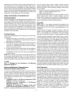
COLD WATER
SHUT-OFF
AQUASTAT
TEMPERATURE
CONTROL
T&P VALVE
DRIP TUBE
DRAIN
VALVE
HOT WATER
OUTLET
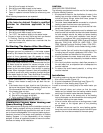
Figure 7 PLUMBING CONNECTIONS
(CENTER FLUE)
150 TO
305mm
6 TO 12”
CENTER OF
BLAST TUBE
NON-COMBUSTIBLE
FLOOR
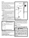
TOP
NIPPLE
BREECH
CONNECTION