


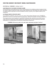

1. Piping should be in accordance with accepted
industry standards. Pipework should be supported
independently of the coils. Water connections are
male NPT iron pipe. When installing couplings, do
not apply undue stress to the connection
extending through the unit. Use a backup pipe
wrench to avoid breaking the weld between coil
connection and header.
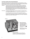
2. Connect the WATER SUPPLY TO THE BOTTOM
CONNECTION on the air leaving side and the
WATER RETURN TO THE TOP CONNECTION on
the air entering side. To insure proper venting, an
external air vent in the piping is recommended.
Connecting the supply and/or return in any other
manner will result in very poor performance. Be
sure to replace factory installed grommets around
coil connections if removed for piping. Failure to
replace grommets will result in water leakage into
the unit and altered performance.
3. The air vent at the uppermost point should be
temporarily opened during system start-up to
release all of the air from the coil. To maintain heat
transfer capacity, periodically vent any air in coil.
4. Water coils are not normally recommended for use
with entering air temperatures below 40
o
F;
however, the energy recovery wheel maintains a
pre-coil temperature higher than 40
o
F. No control
system can be depended on to be 100% safe
against freeze-up with water coils. Glycol
solutions or brines are the only safe media for
operation of water coils with low entering air
conditions.
CONTINUOUS WATER CIRCULATION THROUGH
THE COIL AT ALL TIMES IS HIGHLY
RECOMMENDED.
5. Pipe sizes for the system must be selected on the
basis of the head (pressure) available from the
circulation pump. The velocity should not exceed
6 feet per second and the friction loss should be
approximately 3 feet of water column per 100 feet
of pipe.
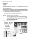
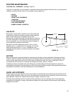
WATER COIL APPLICATION
RECOMMENDATIONS
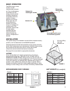
Factory installed heating components are mounted
down stream of the energy wheel on the supply air side
of the unit.
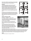
See FIGURE 8 & 9 for coil connection location. Coil
connections are located external to the unit as shown.
Coil connections that are not external have been ordered
from the factory with interior or exhaust air stream coil
connections.
7
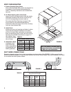
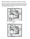
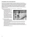
WATER COIL LOCATION AND CONNECTION
A hot water coil can be factory installed in the coil section of the ERH. The coil section is downstream of the
energy wheel on the supply air side of the unit. Coil connections are external to the unit as shown below. Coil
connections not external have been ordered from the factory with internal or exhaust air stream connections.
A
C
B
D
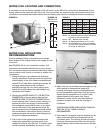
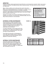
Model A B C D
ERH-20 15 33
3
⁄4 41
1
⁄4 1
1
⁄2 NPT
ERH-45L 17
1
⁄2 39
1
⁄4 46
3
⁄4 1
1
⁄2 NPT
ERH-45H 17
1
⁄
2 48
1
⁄
4 46
3
⁄
4 2 NPT
ERH-55 17
1
⁄2 54
1
⁄4 50
1
⁄2 2 NPT
ERH-90 17
1
⁄2
See Note 5 62
1
⁄4
1
1
⁄2
NPT
TABLE 5
FIGURE 9 FIGURE 10
Note 1: Dimensions shown are for 1-row coil.
Note 2: All dimensions are in inches (measured
to center of coil connections).
Note 3: NPT - National Pipe Thread.
Note 4: ‘A’ dimension assumes a 12 in. curb.
Note 5: The ERH-90 uses a dual coil (stacked
on top of each other). Refer to FIGURE
10 for the ‘B’ dimension.
30
3
⁄4
30
3
⁄4
6
3
⁄4
Top
Coil
Bottom
Coil
ERH-90 Coil
Connections
FIGURE 8
DX coil liquid
connection
access door
Water coil
connections