


4
Model BCSW-FRP
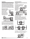
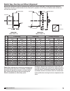
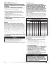
Ducted Outlet Installations
Discharge Duct Turns - Duct turns located near the
fan discharge should always be in the direction of the
fan rotation.
Fan performance is reduced when duct
turns are made immediately off the
fan discharge. To achieve cataloged
fan performance there
should be at least
three equivalent
duct diameters of
straight ductwork
between the fan
discharge and
any duct turns.
Ducted Inlet Installations
Inlet Spin -
Inlet spin is a frequent cause of reduced
fan performance. The change in fan performance is a
function of the intensity of spin and not easily defined.
The best solution is proper duct design and airflow
patterns. Turning vanes reduce the effects of inlet spin.
R
o
t
a
t
i
o
n
R
o
t
a
t
i
o
n
R
o
t
a
t
i
o
n
R
o
t
a
t
i
o
n
Turning
Vanes
Turning
Vanes
POOR
POOR
GOOD
POORGOOD
Length of Straight Duct
GOOD
Three fan wheel diameters
One fan
wheel
diameter
3/4 to
one fan
wheel
diameter
One fan
diameter
3/4 to
one fan
wheel
diameter
SYSTEM EFFECT FACTORS CURVES
STATIC PRESSURE LOSS
1.2
1.0
0.8
0.6
0.4
0.2
0.0
0 5 10 15 20 25 30 35 40 45
FPM X 100
OUTLET VELOCITY
CURVE 1
CURVE 2
CURVE 3
CURVE 4
R
o
t
a
t
i
o
n
R
o
t
a
t
i
o
n
R
o
t
a
t
i
o
n
R
o
t
a
t
i
o
n
Turning
Vanes
Turning
Vanes
POOR
POOR
GOOD
POORGOOD
Length of Straight Duct
GOOD
Three fan wheel diameters
One fan
wheel
diameter
3/4 to
one fan
wheel
diameter
One fan
diameter
3/4 to
one fan
wheel
diameter
SYSTEM EFFECT FACTORS CURVES
STATIC PRESSURE LOSS
1.2
1.0
0.8
0.6
0.4
0.2
0.0
0 5 10 15 20 25 30 35 40 45
FPM X 100
OUTLET VELOCITY
CURVE 1
CURVE 2
CURVE 3
CURVE 4
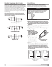
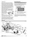
Parallel Fan Installation
Non-Ducted Installations
Inlet Clearance - Installation of a fan with an open
inlet too close to a wall or bulkhead will cause
reduced fan performance. It is desirable to have
one fan wheel diameter between parallel fan units
and a minimum of three-fourths of a wheel diameter
between the fan inlet and the wall.
Free Discharge - Free or abrupt discharge into a
plenum results in a reduction in fan performance. The
effect of discharge static regain is not realized.
R
o
t
a
t
i
o
n
R
o
t
a
t
i
o
n
R
o
t
a
t
i
o
n
R
o
t
a
t
i
o
n
Turning
Vanes
Turning
Vanes
POOR
POOR
GOOD
POORGOOD
Length of Straight Duct
GOOD
Three fan wheel diameters
One fan
wheel
diameter
3/4 to
one fan
wheel
diameter
One fan
diameter
3/4 to
one fan
wheel
diameter
SYSTEM EFFECT FACTORS CURVES
STATIC PRESSURE LOSS
1.2
1.0
0.8
0.6
0.4
0.2
0.0
0 5 10 15 20 25 30 35 40 45
FPM X 100
OUTLET VELOCITY
CURVE 1
CURVE 2
CURVE 3
CURVE 4
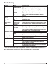
Inlet Duct Turns - Installation of a duct turn or elbow
too close to the fan inlet
reduces fan performance
because air is loaded
unevenly into the fan
wheel. To achieve full fan
performance, there should
be at least three fan wheel
diameter between the turn
or elbow and the fan inlet.
R
o
t
a
t
i
o
n
R
o
t
a
t
i
o
n
R
o
t
a
t
i
o
n
R
o
t
a
t
i
o
n
Turning
Vanes
Turning
Vanes
POOR
POOR
GOOD
POOR
GOOD
Length of Straight Duct
GOOD
Three fan wheel diameters
One fan
wheel
diameter
3/4 to
one fan
wheel
diameter
One fan
diameter
3/4 to
one fan
wheel
diameter
SYSTEM EFFECT FACTORS CURVES
STATIC PRESSURE LOSS
1.2
1.0
0.8
0.6
0.4
0.2
0.0
0 5 10 15 20 25 30 35 40 45
FPM X 100
OUTLET VELOCITY
CURVE 1
CURVE 2
CURVE 3
CURVE 4
R
o
t
a
t
i
o
n
R
o
t
a
t
i
o
n
R
o
t
a
t
i
o
n
R
o
t
a
t
i
o
n
Turning
Vanes
Turning
Vanes
POOR
POOR
GOOD
POOR
GOOD
Length of Straight Duct
GOOD
Three fan wheel diameters
One fan
wheel
diameter
3/4 to
one fan
wheel
diameter
One fan
diameter
3/4 to
one fan
wheel
diameter
SYSTEM EFFECT FACTORS CURVES
STATIC PRESSURE LOSS
1.2
1.0
0.8
0.6
0.4
0.2
0.0
0 5 10 15 20 25 30 35 40 45
FPM X 100
OUTLET VELOCITY
CURVE 1
CURVE 2
CURVE 3
CURVE 4
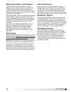
Installation
Installations with inlet or discharge configurations
that deviate from this standard may result in reduced
fan performance. Restricted or unstable flow at the
fan inlet can cause pre-rotation of incoming air or
uneven loading of the fan wheel yielding large system
losses and increased sound levels. Free discharge
or turbulent flow in the discharge ductwork will also
result in system effect losses. Refer to the following
diagrams for the most efficient installation conditions.
R
o
t
a
t
i
o
n
R
o
t
a
t
i
o
n
R
o
t
a
t
i
o
n
R
o
t
a
t
i
o
n
Turning
Vanes
Turning
Vanes
POOR
POOR
GOOD
POORGOOD
Length of Straight Duct
GOOD
Three fan wheel diameters
One fan
wheel
diameter
3/4 to
one fan
wheel
diameter
One fan
diameter
3/4 to
one fan
wheel
diameter
SYSTEM EFFECT FACTORS CURVES
STATIC PRESSURE LOSS
1.2
1.0
0.8
0.6
0.4
0.2
0.0
0 5 10 15 20 25 30 35 40 45
FPM X 100
OUTLET VELOCITY
CURVE 1
CURVE 2
CURVE 3
CURVE 4
R
o
t
a
t
i
o
n
R
o
t
a
t
i
o
n
R
o
t
a
t
i
o
n
R
o
t
a
t
i
o
n
Turning
Vanes
Turning
Vanes
POOR
POOR
GOOD
POORGOOD
Length of Straight Duct
GOOD
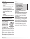
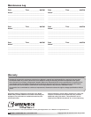
1 Fan
Wheel
Diameter
One fan
wheel
diameter
One fan
wheel
diameter
3/4 to one
fan
wheel
diameter
One fan
diameter
3/4 to one
fan
wheel
diameter
SYSTEM EFFECT FACTORS CURVES
STATIC PRESSURE LOSS
1.2
1.0
0.8
0.6
0.4
0.2
0.0
0 5 10 15 20 25 30 35 40 45
FPM X 100
OUTLET VELOCITY
CURVE 1
CURVE 2
CURVE 3
CURVE 4
Single Fan Installation