


6
Model VSU Make-Up Air
®
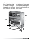
Burner Subassembly
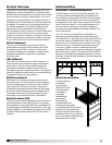
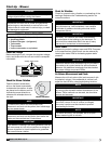
The burner subassembly consists of the gas train with
its controls, valves, pressure regulator, burner(s), and
combustion chamber. The primary gas connection to
the gas train is made through the side wall grommet
into the factory-supplied female pipe fitting.
Gas Train
(Burner Subassembly)
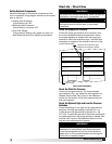
Control Center
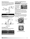
The control center is located on the end of the unit,
directly above the gas train access door. The control
center contains electronic components and some
elctromechanical devices that monitor and control
the operation of the entire unit. A unit-specific wiring
diagram is affixed to the inside of the access door.
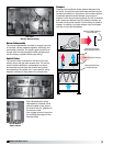
High voltage supply wiring
terminates at a manual on/off
switch located on the face or
the side of the unit, adjacent to
the control center.
Low voltage control wiring from
the building terminates on the
terminal strips.
Manual High Voltage
On/Off Switch
with Lockout
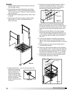
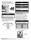
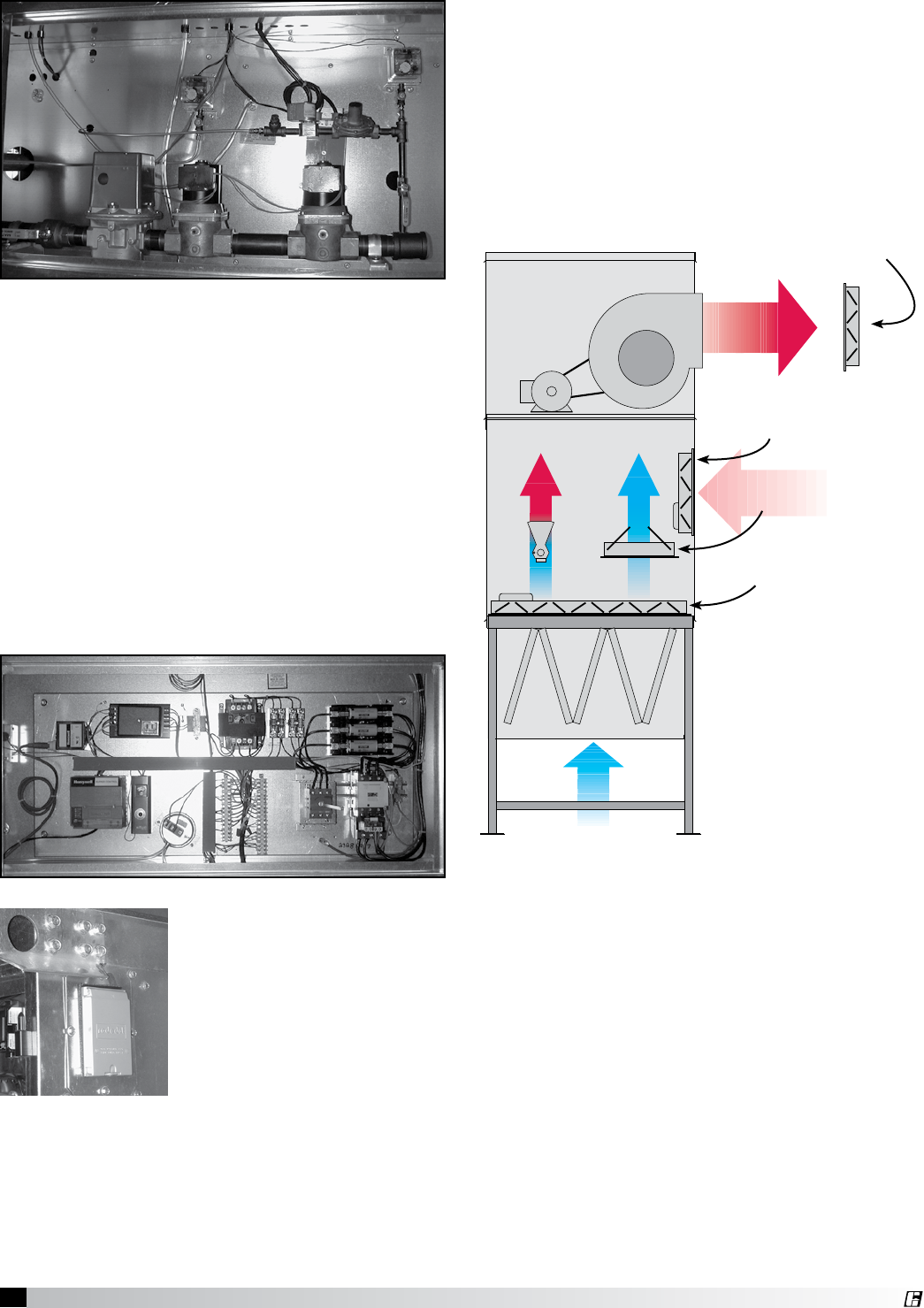
Dampers
There are four locations where optional dampers may
be found. An optional motorized intake damper may be
located horizontally on the bottom of the burner section.
A patented passive control damper may be found
adjacent to the burner opening plates if a VAV is ordered
and a motorized damper may be installed vertically on
the side of the burner section if recirculating air mode is
chosen. In addition, an outlet damper may be shipped
with the unit for field installation.
Optional Field-Installed
Outlet Damper
Optional Motorized
Recirculating Damper
Passive Control Damper
Optional Motorized
Intake Damper