


5
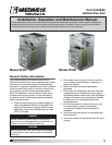
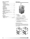
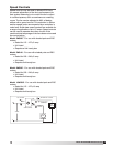
Model VFCD/VFCB Vertical Fan Coil
®
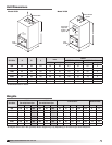
Coil Dimensions
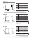
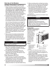
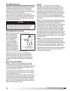
NOTE
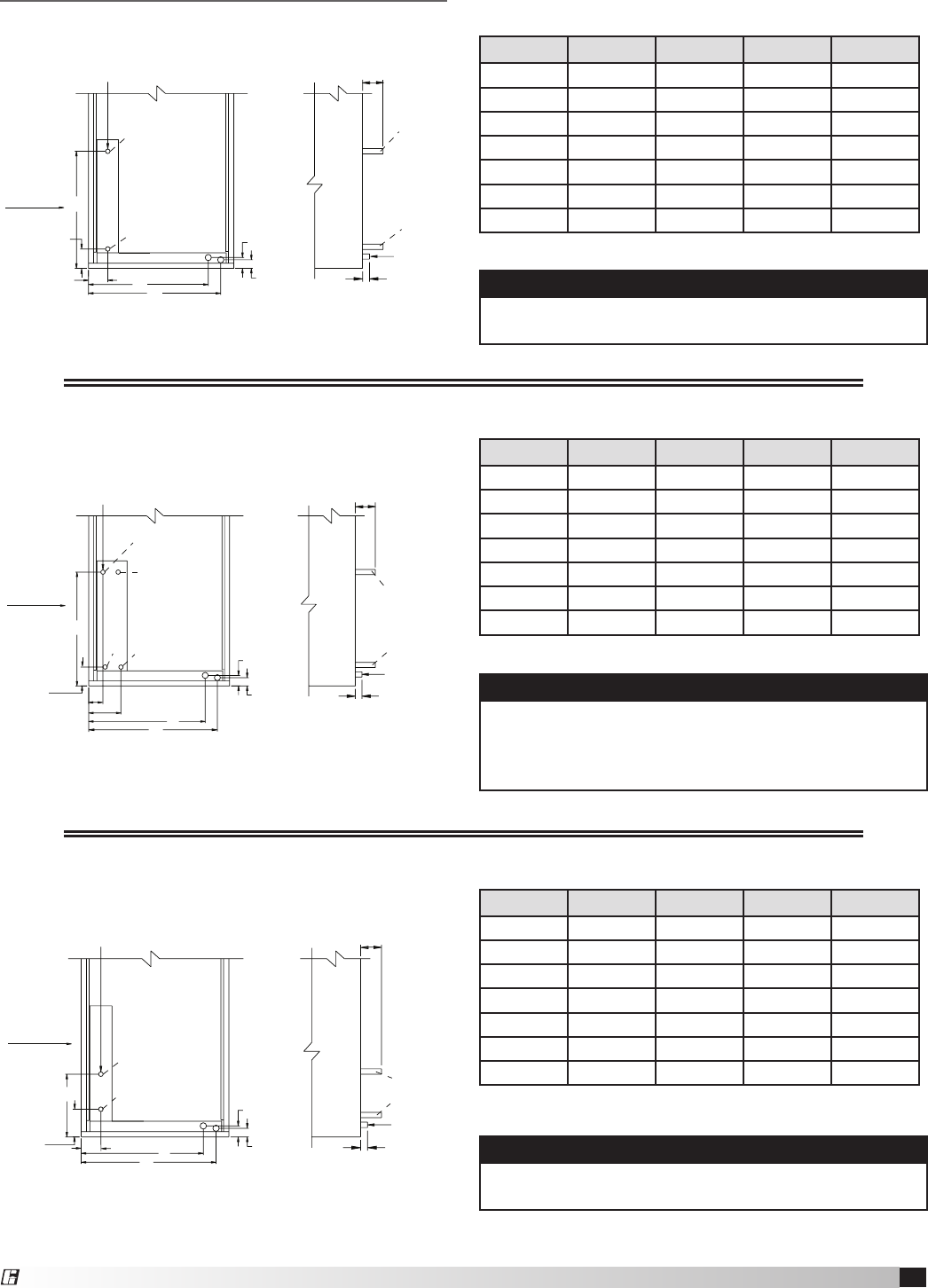
Fluid enters the coil from the bottom connection
(Inlet) and exits from the top (Outlet).
Hot Water • 1 and 2 Row
Unit Size A B C D
600 20.00 22.50 22.63 0.875
800 20.00 22.50 22.63 0.875
1300 24.00 27.50 22.63 0.875
1600 24.75 27.25 22.63 0.875
2000 24.75 27.50 25.13 0.875
2400 24.75 27.50 25.13 0.875
3000 28.75 31.25 22.63 1.375
All dimensions are in inches.
HEAT-1 & 2 ROW HW
B
A
3.81 in.
3.75 in.
C
D
2 in.
1.5 in.
4 in.
0.75 in.
1 in.
Outlet
Drain
Connection
Outlet
Inlet
Inlet
Airflow
0.25 vent and drain supplied. Right side connection shown.
NOTE
With airflow from left to right, the fluid enters the coil
from the bottom connection (Inlet) and exits from the
top (Outlet). The other two coil connections should
be capped off (Cap).
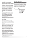
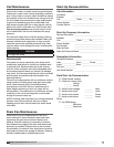
Hot Water • 4 Row
Unit Size A B C D
600 20.00 22.50 22.63 0.875
800 20.00 22.50 22.63 0.875
1300 24.00 27.50 22.63 0.875
1600 24.75 27.25 22.63 0.875
2000 24.75 27.50 25.13 0.875
2400 24.75 27.50 25.13 0.875
3000 28.75 31.25 22.63 1.375
All dimensions are in inches.
0.25 vent and drain supplied. Right side connection shown.
A
6.63 in.
3.38 in.
C
B
D
1.5 in.
2 in.
3 in.
0.75 in.
1 in.
Outlet
Drain
Connection
3.75 in.
Outlet
Inlet
Inlet
Cap
Cap
4 ROW HW
Airflow
NOTE
Steam enters the coil from the center connection
(Inlet) and exits from the bottom (Outlet).
Unit Size A B C D
600 20.00 22.50 13.20 2.0
800 20.00 22.50 13.20 2.0
1300 24.00 27.50 13.20 2.0
1600 24.75 27.25 13.20 2.0
2000 24.75 27.50 14.44 2.0
2400 24.75 27.50 14.44 2.0
3000 28.75 31.25 13.20 2.5
All dimensions are in inches.
Right side connection shown.
HEAT-1 ROW ST
D
C
4.38 in.
5 in.
A
B
1.5 in.
2 in.
3 in.
0.75 in.
1 in.
Outlet
Drain
Connection
Inlet
Outlet
Inlet
Airflow
Steam • 1 and 2 Row