


684025 7
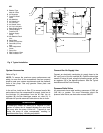
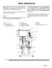
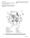
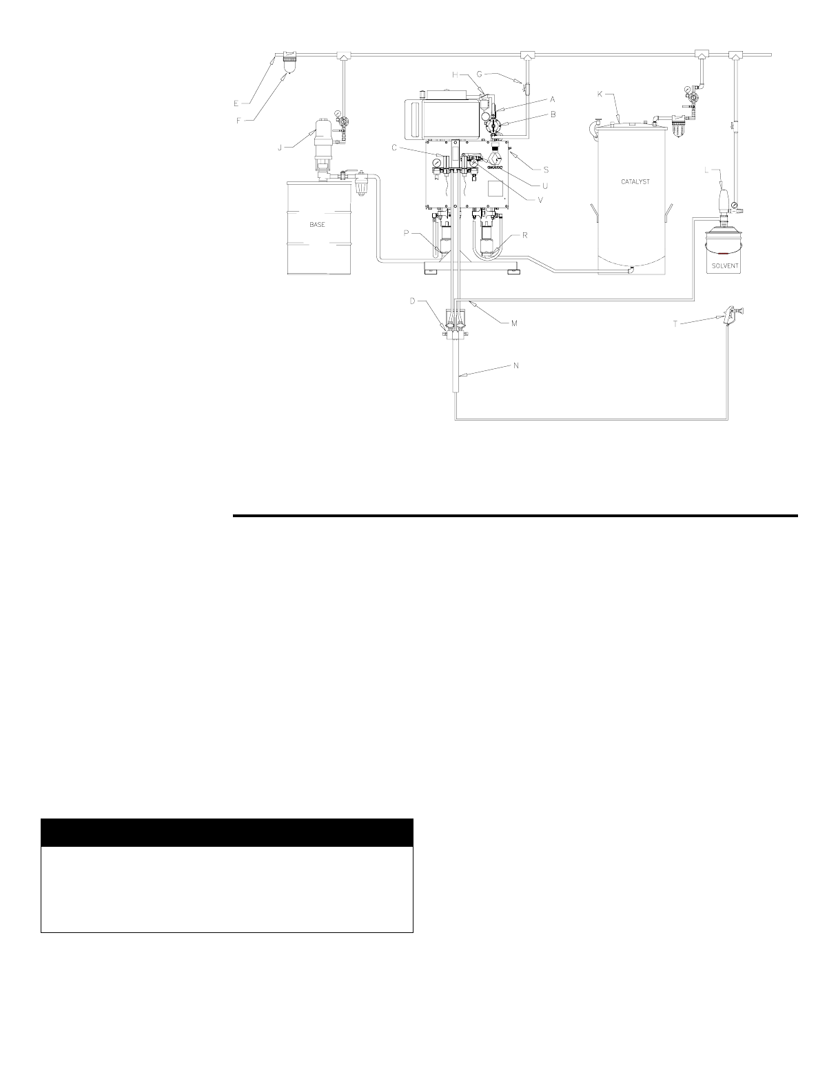
KEY
A Bleeder Type
Main Air Valve
B Air Regulator
C Pressure Relief
Valve
D Mix Manifold
E Air Supply Line
F Air Line Filter
G Air Shutoff Valve
H Air Line Lubricator
J Base Supply Pump
K Catalyst Supply
Pressure Pot
L Solvent Supply
Pump
M Mix Manifold Flush
Inlet
N Static Mixer
P Primary Pump Inlet
R Secondary Pump
Inlet
S Ratio Adjustment
Screw
T Spray Gun
U Ratio Indicator Plate
V Ratio Indicator Pin
Fig. 2 Typical Installation
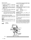
System Accessories Connect the Air Supply Line
Refer to Fig. 2.
NOTE:
To ensure the maximum pump performance and
safety, be sure that all the accessories used are properly
sized to meet your system requirements and the pressure
limits of the pump. Use only
g
enuine Graco parts and
accessories.
In the air line, install an air filter (F) to remove harmful dirt
and moisture from the compressed air supply. Install an air
line lubricator (H) downstream from the air filter, the air
re
g
ulator (B) and the bleed-type master air valve (A). A
lubricator will provide automatic lubrication to the air motor.
Connect an electrically conductive air supply hose to the
3/4” npt(f) port of the air manifold (B). Open the bleed-type
master air valve (A) and, usin
g
the pressure
g
au
g
e, set the
air re
g
ulator (B) to the desired pressure. See the Typical
Installation and the Parts Drawing.
Pressure Relief Valve
All components have rated workin
g
pressures of 5000 psi
(345 bar) or
g
reater. For more information about the
pressure relief valve, see instruction manual 308547.
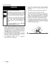
WARNING
A bleed-type master air valve (A) is required in your
system to relieve the air trapped between the valve and
the pump after the pump is shut off. Trapped air can
cause the pump to cycle unexpectedly, resultin
g
in
possible serious injury, including amputation.