Installation
6 311304H
Installation
When unpacking pump, check for shipping damage.
Report any shipping damage to delivering carrier imme-
diately.
Mounting Pump
1. Apply PTFE thread tape (provided with the pump) to
large thread of bung adapter (9) (2 in. X 1 ½ in.
reducer fitting). Install bung adapter to fuel tank.
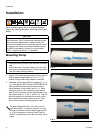
2. Assemble suction tube sections by applying ¼ in. to
½ in. wide bead of PVC cement (PN: 260086; white
tube provided with the pump) around the entire
inside diameter of the coupler (see F
IG. 1). While
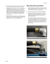
sliding the tube into the couplers turn the tube at
least one full revolution until the tube bottoms out on
the coupler (see F
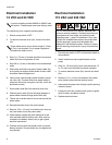
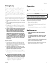
IG. 2, FIG. 3, and FIG. 4). This will
allow the cement to coat the entire surface for the
best possible seal. Allow cement to set for 5 min-
utes minimum before installing pump into tank.
CAUTION
Do not use a curb pump automatic shut-off nozzle
with this pump. Use of a curb pump automatic nozzle
may cause priming problems, reduced output flow,
and motor overheating. If an automatic shut-off nozzle
is required, use Graco part number 260082 (regular)
or 260083 (unleaded) or Catlow, Inc. part number
NCLF-1 (regular) or NCNLF-1 (unleaded).
CAUTION
• Ensure tank being used is clean and free of welding
slag
• Ensure the tank is vented to allow air into the tank
as the fuel is being pumped out. Failure to provide a
vent will cause priming problems
For tanks deeper than 36 in. (914 mm) you will
need a standard 1 in. (25 mm) pipe with 1 in. npt
threads on one end. Suction tubes longer than 60
in. (1.52 m) require a foot valve (Graco Part No.
260217) at the bottom of the tube to prevent loss of
prime.
FIG. 1
F
IG. 2
F
IG. 3
F
IG. 4


