


4 312933D
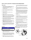
X5, X7, LTS 15, and LTS 17 Pressure Control Replacement
Disassembly
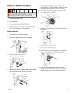
1. Unplug electrical cord and Relieve Pressure. See
Pressure Relief Procedure on page 3.
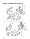
2. X7 and LTS 17 Only: Remove underside shroud
mounting screw (D).
3. Remove side shroud screws (E) (T-20 Torx).
4. Remove 4 front cover screws (F) (T-30 Torx).
5. Remove shroud (G).
6. Disconnect power cord connectors (H) from
ON/OFF switch (L).
7. Remove shroud (K).
8. Series A: Remove 2 pump housing mounting
screws (ps). Be sure to support pump housing (ph).
9. Series A: Remove pump housing (ph). X7 and LTS
17 Only: Pull power cord (N) through opening in
pump housing mounting bracket (pb).
10. Disconnect pressure control harness from control
board connector (cb). Take note of wire routing; new
wires will be rerouted the same way.
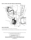
11. Series A: Remove AutoPrime cover (A) by releas-
ing tab underneath pressure control knob.
Series B: Release tab underneath function indicator
(fi) and remove indicator and front cover.
12. Turn pressure control knob fully counterclockwise to
expose wrench flats. Remove pressure control (P).
Verify the o-ring seal (or) has been removed from
the pump (J).
Assembly
1. Examine new pressure control (P) to verify o-ring
seal (or) is in place. If o-ring seal is not installed on
pressure control, install seal.
2. Apply one or two drops of thread locking adhesive
(included in kit) to threads of pressure control switch
(P). Assemble pressure control switch (P) into pump
(J). Torque to 140-160 in.-lbs (16-18 N•m).
3. Series A: Route pressure control (P) harness as
shown in harness routing detail on page 12. Con-
nect to control board connectors (cb) (connect with
tab in front). Install AutoPrime cover (A) and latch
tab.
4. Install pump housing (ph) with 2 pump housing
mounting screws (ps) onto pump housing mounting
bracket (pb). Torque to 110 to 120 in-lb (12.4 to 13.6
N•m).
5. Series B: Route pressure control harness through
function indicator (fi) and front cover. Install indicator
on pump and snap together. Align indicator and
front cover as they are positioned loosely on pump.
Connect harness to control board terminals (cb).
6. Reattach power cord connectors (H) to ON/OFF
switch (L).
7. Install shroud (K).
8. X7 and LTS 17 Only: Route power cord (N) through
opening in pump housing mounting bracket (pb).
9. Install power cord (N) into recess on left shroud (K).
10. Install shroud (G) to shroud (K) and front cover.
11. Install side shroud screws (E) (T-20 Torx). Torque to
20 to 25 in-lb (2.3 to 2.8 N•m).
12. Install 4 front cover screws (F) (T-30 Torx). Torque
to 26 to 32 in-lb (2.9 to 3.6 N•m).
13. X7 and LTS 17 Only: Install underside shroud
mounting screw (D). Torque to 25 to 35 in-lb (2.8 to
3.9 N•m).
14. Turn pressure control switch knob (P) clockwise as
far as it will go. Apply pressure control label (cl) to
knob. To position label correctly, see note below:
NOTE: When properly positioned, the function indicator
(fi) and hi-spray position symbol on pressure control
label (cl) are aligned.
NOTICE
Do not pinch wires between pressure control (P) and
pump housing (ph) pump mounting bracket (pb) and
shrouds (G and K) while assembling.
fi
P
cl
ti10041a
hi-spray symbol