


Air Motor and Throat Service
309966H 13
Reassembly
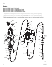
1. Clean all the parts carefully in a compatible solvent,
and inspect for wear or damage. Use all the repair
kit parts during reassembly, and replace other parts
as necessary.
2. Check the polished surfaces of the piston (2), dis-
placement rod (8), and cylinder (17) wall for
scratches or wear. A scored rod causes premature
throat seal wear and leaking.
3. Lubricate all parts with a light, water–resistant
grease.
4. Install the new throat seal (6), lips facing down.
Screw the packing nut (38) into the base (5).
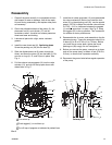
5. Slide the displacement rod (8) down through the
throat, and lower the piston (2) into the base (5). Be
sure the o–rings (9, 10, and 24) are in place. See
Fig. 4.
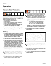
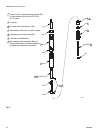
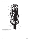
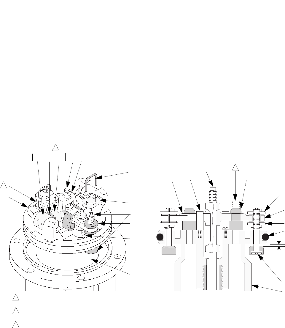
6. Pull the exhaust valve poppets (16) into the valve
actuator (13), and clip off the top part shown with
dotted lines in Fig. 5.
7. Install the air intake grommets (12), and reassemble
the valve mechanism. Before you install the lock-
wires (31) in the adjusting nuts (30), use the special
gauge, 15E796, to adjust the transfer valve so there
is 0.105 +
.010 in. clearance between the poppets
(1) and the seat when it is open. See Fig. 5. Snap
the toggles (25) to the up position. This is essential
for reliable air motor performance.
8. Reassemble the air motor, and assemble to the dis-
placement pump. Torque the extension tube (64) to
to base (5) at 45 to 55 ft-lb (61 to 75 N•m). Before
you install the air motor plate, tighten the throat
packing nut (38) snugly; do not overtighten it.
9. Before you remount the pump, connect an air hose,
and run the pump slowly, at about 40 psi (276 kPa,
2.8 bar), to ensure that it operates smoothly.
10. Reconnect the ground wire before regular operation
of the pump.
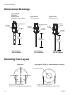
F
IG. 6
0.105 in.
(2.7 mm)
Turn wires up.
Push toggles (L) in and then up.
Cut off tops of poppets as indicated by dotted lines
1
2
3
1
30
31
22
11
25
27
26
M
12
13
30
2
12
14
11
16
30
24
1
2
L
30
1
2
3
Cutaway View
04118
04119