


All written and visual data contained in this document reflects the latest product information available at the time of publication.
Graco reserves the right to make changes at any time without notice.
Original instructions. This manual contains English. MM 333488
Graco Headquarters: Minneapolis
International Offices: Belgium, China, Japan, Korea
GRACO INC. AND SUBSIDIARIES • P.O. BOX 1441 • MINNEAPOLIS MN 55440-1441 • USA
Copyright 2014, Graco Inc. All Graco manufacturing locations are registered to ISO 9001.
www.graco.com
May 2014
Instructions
Pressure Relief Procedure
Follow the Pressure Relief Procedure whenever you
see this symbol.
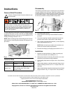
To relieve pressure in the system, use two wrenches working
in opposite directions on pump outlet fitting to slowly loosen
fitting only until fitting is loose and no more lubricant or air is
leaking from fitting as shown in FIG. 1.
NOTE: When loosening pump element fitting do NOT loosen
pump element. Loosening pump element will change the out-
put volume.
Technical Data
Disassembly
The following instructions are for removing the pump element
currently installed in the G3 Pump. Reference numbers used
in these instructions correspond to parts included in the kit and
are provided on page 1. Parts identified with an alpha charac-
ter are user provided or already installed components.
1. Disconnect power source.
2. Relieve pressure following Pressure Relief Procedure
provided.
3. Disconnect anything installed to pump element such as
pressure relief valves, output union or other fittings.
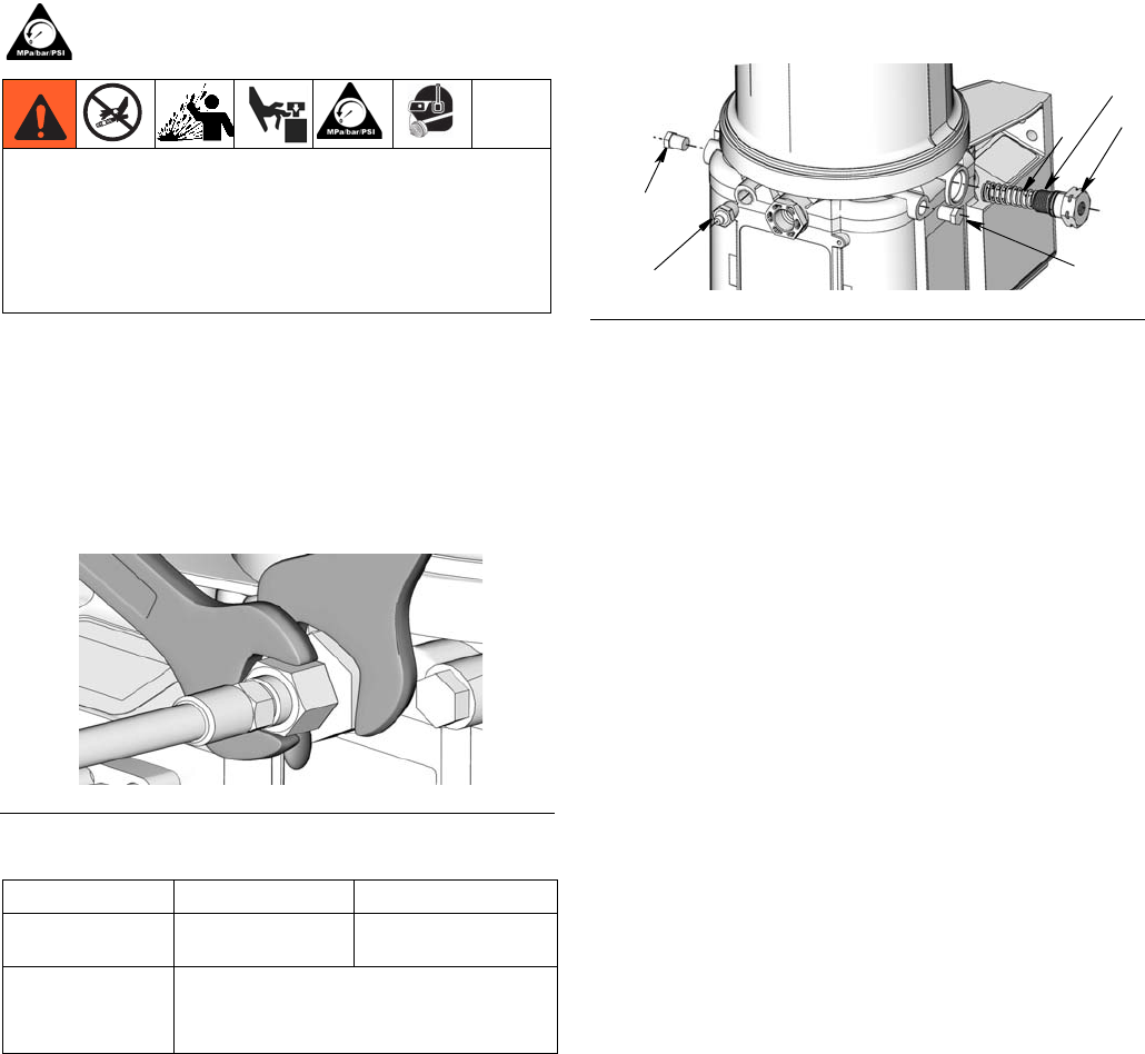
4. Use a wrench to loosen pump element (1) and completely
remove pump element (F
IG. 2).
NOTE: Make sure spring (a) retainer (b) and piston (not
shown) are removed with pump element.
5. Remove zerk fitting (2) and plugs (3) as shown in F
IG. 2.
Installation
1. Examine new pump element (1). Make sure spring (a),
retainer (b) and piston are installed (FIG. 2).
2. Slide pump element into housing. Be careful not to cross
thread the pump element during installation.
3. Hand tighten pump and then torque to 50 in.-lbs (5.6 N•m)
(F
IG. 1).
4. Apply thread sealant to stainless steel zerk fitting (2) and
install zerk fitting as shown in F
IG. 2. Torque to 50 in.-lbs
(5.6 N•m).
5. Apply thread sealant to stainless steel plugs (3) and install
plugs as shown in Fig. 2. Torque to 50 in.-lbs (5.6 N•m).
This equipment stays pressurized until pressure is
manually relieved. To help prevent serious injury from
pressurized fluid, such as skin injection, splashing fluid and
moving parts, follow the Pressure Relief Procedure when
you stop dispensing and before cleaning, checking, or
servicing the equipment.
FIG. 1
US Metric
Maximum Working
Pressure
5100 psi 35.1 MPa, 351.6 bar
Wetted Parts
nylon 6/6 (PA), zinc plated steel, alloy
steel, stainless steel, nitrile rubber
(buna-N), PTFE
FIG. 2
1
a
b
3
2
3