


Installation
306287W 5
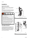
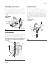
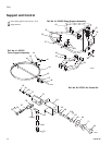
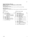
Pump Support Bracket
Set an open drum against the elevator base (17). Posi-
tion the bracket (40) on top of the drum so that the
clamp (34) recesses are tight against the elevator riser
tube (14 or 28). See F
IG
. 1 and F
IG
. 3. Raise the riser
tube up about 0.25 in. (6.4 mm), install the clamps (34)
and tighten securely. Attach the pump mounting brack-
ets (38)
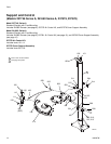
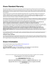
Cover Support
Place the cover in its proper position in the support ring
(49) and tighten the capscrews (45). Set an open drum
against the elevator base (17) and put the cover on the
drum so the support clamp (44) recesses are tight
against the elevator riser tube (14 or 28). Raise the tube
0.25 in. (6.4 mm), then tighten the clamp screws (42).
See F
IG
. 4.
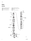
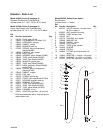
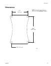
Air Connection
Screw the restrictor valve (55) into the push-pull valve
(60) as shown in F
IG
. 5. Mount the valve on the wall at a
convenient height, using the mounting bracket (54).
Connect the master air supply to the valve. Screw the
elbow fitting (52) into the 1/8 npt(f) inlet of the restrictor
valve. Push one end of the copper tube (51) into the
elbow and tighten the fitting. Screw the straight fitting
(53) into the base (17) of the elevator. Push the other
end of the copper tube (51) into this fitting and tighten
the fitting.
F
IG
. 3
F
IG
. 4
Pump Support
Ref. No. 31
06528
40
38
34
06529b
49, 45
45
49
48
17
44, 42
14 or 28
F
IG
. 5
Push-Pull Valve
Ref. No. 60
06531
54
60
55
52
51