


Fig. 3
M
E
F
H
0232
5
J
8 307843
Installation
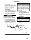
Connect the Fluid Lines
1. Use grounded fluid hoses.
a. The pump fluid outlet (J) on the 400 and
1200 Series Pumps is 1 npt(f) .
b. The pump fluid outlet (J) on the 2500 Series
Pump is 3/4 npt(f).
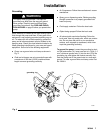
2. Install a fluid filter (F) and drain valve (E) near the
fluid outlet. See Fig. 3.
WARNING
A fluid drain valve (E) is required in your system to
relieve pressure in the fluid outlet hose (H) if the
hose becomes plugged. See Fig. 3. Install a drain
valve close to the pump’s fluid outlet. The drain
valve reduces the risk of property damage or
serious bodily injury, including splashing in the eyes
or on the skin, or contamination from hazardous
fluids.
3. Install a control device, such as a gun, dispensing
valve, or shutoff valve, on the grounded fluid
hose (H).
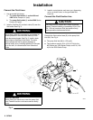
Connect the Fluid Suction Line
CAUTION
The pump must be suction fed in order to operate
properly. Pressure feeding or exceeding 15 psi (104
kPa, 1.04 bar) maximum fluid inlet pressure may
cause premature bellows seal failure.
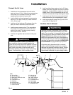
Connect the fluid suction hose (S) to the pump fluid
inlet (M). See Fig. 4.
D The pump fluid inlet (M) is 1.25 npt(f).
D The maximum suction lift is 15 ft (4.57m) for the
400 Series and 1200 Series Pumps, and 6 ft (1.83
m) for the 2500 Series Pump.
WARNING
SUCTION HAZARD
Never place your hands on or near the pump fluid
inlet. Powerful suction could cause serious bodily
injury.