4
306–646
INSTALLATION
E
F
H
J
K
D
L
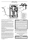
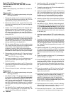
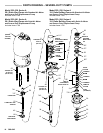
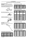
KEY
A
Air Supply Hose to Pump
B
Air Line Filter
C
Air Regulator and Gauge
D Bleed–T
ype Master Air V
alve
E
Air Line Lubricator
F
Pump Runaway V
alve
G Bleed–T
ype Master Air V
alve
H
Fluid Drain V
alve
J
Air–Powered Ram
K
Gun/Dispensing V
alve
L
Grounded Fluid Supply Hose
M
Whip Hose
N
Air Supply Hose to Ram
Y
Pump Ground Wire
4
Pump Bleeder V
alve
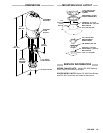
TYPICAL
INST
ALLATION
G
A
M
N
C
B
Y
4
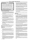
The
reference numbers and
letters in the text refer to the
callouts
in Figures 1–3 and the Parts Drawings.
See
pages 16–18 for accessories
available from Graco.
Be sure all accessories are properly sized to withstand
the
pressures in the system.
The Typical Installation shown above is only a guide to
selecting and installing required and optional accesso-
ries. For assistance in designing a system to suit your
particular
needs, contact your Graco representative.
The Dimensional Drawing on page 19 provides neces-
sary
measurements for mounting the pump. If you use an
accessory ram (J), as shown in the T ypical Installation,
refer
to the separate ram manual for mounting dimension
requirements.
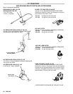
System
Accessories
Install the air line accessories in the order shown in the
Typical
Installation. W
orking upstream from the pump air
inlet, install a pump
runaway valve (F) to shut of
f the air to
the pump if the pump accelerates beyond the pread-
justed setting. A pump which runs too fast can be seri-
ously
damaged.
Next,
install an air line lubricator (E) for automatic air
mo
-
tor lubrication, a bleed–type master air valve (D) to re-
lieve
air trapped between the valve
and the pump, an air
regulator
(C) to control pump
speed, and an air line filter
(B) to remove harmful dirt and moisture from the com-
pressed air supply. Install a second bleed valve (G) on
the
pump air line to isolate the accessories for servicing.
Be
sure the pump air line (A) is properly grounded, and is
large
enough to supply
an adequate volume of air to the
motor. An air–powered ram (J) requires a separate
grounded
air supply line (N).
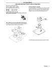
WARNING
Two accessories are required in your system: a
bleed–type master air valve (D) and a fluid drain
valve
(H).
These accessories help reduce the risk of
serious bodily injury including fluid injection, splash
-
ing
in the eyes or on the skin, and injury from moving
parts
if you are adjusting or repairing the pump.
The
bleed–type master air valve
relieves air trapped
between
this valve and
the pump after the air is shut
off.
T
rapped air can cause the pump to cycle unex
-
pectedly.
Locate the valve close to the pump.
The
fluid drain valve
assists in relieving fluid pres-
sure
in
the displacement pump, hose and spray gun;
triggering
the spray gun to relieve pressure may not
be
suf
ficient.
Install
a fluid drain valve (H) close to the pump fluid
outlet.
Then connect a grounded fluid supply hose (L). Be-
tween the fluid supply hose (L) and the gun/dispensing
valve
(K), install a whip hose (M) for greater flexibility
.
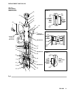
NOTE: To
use the optional fluid outlet at the base of
the
air
motor
, connect a riser tube between the stan
-
dard
outlet and the optional outlet.
GROUNDING
WARNING
Before operating the pump, ground the system as
explained under FIRE OR EXPLOSION HAZARD
and
Grounding
on page 3.