8 306878
Maintenance
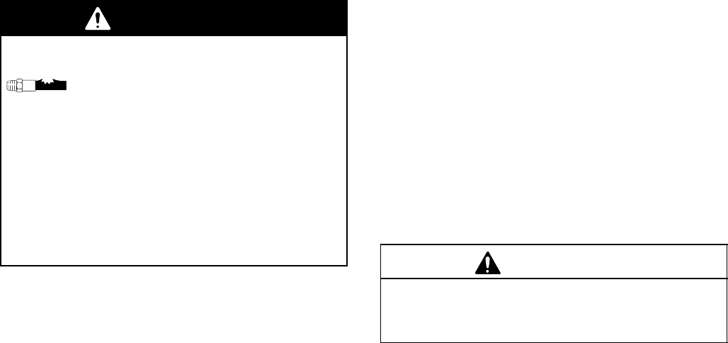
WARNING
COMPONENT RUPTURE HAZARD
To reduce the risk of serious bodily inju-
ry, including fluid injection or splashing in
the eyes or on the skin, always follow
the Pressure Relief Procedure on page 7 before
adjusting, cleaning, repairing, or removing the regu-
lator from the system.
Never pressurize the system with the fluid regula-
tor adjusting knob removed.
Never completely remove the adjusting knob when
system pressure is present.
Flushing
D Flush before changing colors, before fluid can dry in
the equipment, at the end of the day, before storing,
and before repairing equipment.
D Flush at the lowest pressure possible. Check
connectors for leaks and tighten as necessary.
D Flush with a fluid that is compatible with the fluid
being dispensed and the equipment wetted parts.
1. Record the pressure adjustment setting of the
regulator before flushing.
2. Shut off the pump and relieve fluid pressure in the
system by triggering the gun and opening the back
pressure valve or other bypass valve.
3. Never exceed the maximum working pressure of
the lowest rated system component.
4. Open the fluid regulator by turning the adjusting
knob (6) fully clockwise.
5. Supply solvent to the system. Set pump to the
lowest possible pressure, and start pump.
6. Flush until thoroughly clean.
7. Adjust the fluid regulator to return to the desired
fluid pressure setting.
NOTE: Do not allow paint or solvent to set in the
system for a long time. Fluid could dry on the piston,
causing leakage at the piston packing. If leakage
occurs, disassemble and clean the regulator.
Cleaning
When changing fluids or colors, the regulator should
be disassembled and cleaned. Regular cleaning and
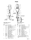
inspection, and lubrication of the piston (15) and piston
packing (10) are necessary to keep the fluid regulator
working properly.
1. Relieve all the air and fluid pressure in the system.
2. Remove the regulator from the system.
3. Disassemble the regulator, referring to the Parts
Drawing on page 9. Clean and inspect all parts.
CAUTION
Use special care when handling the hard carbide
portions of the piston (13) and seat (12). Damage will
cause poor operation and leakage.
Repairing
Normally, only the ball support (21), seat (20) and
piston packing (10) will ever need replacement. Repair
Kit 220139 is available to replace these parts. See
page 9.
1. Lubricate the piston packing (10), piston (15), and
spring locater (11) with lithium base grease.
2. Place the washer (19) over the pointed end of the
piston (15).
3. Place the packing (10), with its lips facing down,
over the pointed end of the piston (15) and against
the washer (19).
4. Insert the piston (15) into the bottom of the cylin-
der (7) and gently work it into place.
5. Reassemble the remaining parts in reverse order
of disassembly. Torque the valve seat (20) into the
housing to 175 to 200 in-lb (20 to 22 NSm). Over
tightening could break off the hex portion of the
seat.


