


13
11. Slowly raise the heating temperature setting. When
the heating first stage makes contact, stop raising the
temperature setting.. The compressor, blower and fan
should now be running with the reversing valve in the
de-energized (heating) position. After giving the unit
time to settle out, make sure the unit is supplying
heated air.
12. If the outdoor ambient is above 80°F, the unit may trip
on its high pressure cut out when on heating. The
compressor should stop. The heating cycle must be
thoroughly checked, so postpone the test to another
day when conditions are more suitable but-DO NOT
FAIL TO TEST.
If the outdoor ambient is low and the unit operates
properly on the heating cycle, you may check the
pressure cutout operation by blocking off the indoor
return air until the unit trips.
13. If unit operates properly in the heating cycle, raise
the temperature setting until the heating second stage
makes contact. Supplemental resistance heat, if
installed should now come on. Make sure it operates
properly.
NOTE: If outdoor thermostats are installed the
outdoor ambient must be below the set point of these
thermostats for the heaters to operate. It may be
necessary to jumper these thermostats to check
heater operation if outdoor ambient is mild.
14. For thermostats with emergency heat switch, return
to step 11. The emergency heat switch is located at
the bottom of the thermostat. Move the switch to
emergency heat. The heat pump will stop, the blower
will continue to run, all heaters will come on and the
thermostat emergency heat light will come on.
15. If checking the unit in the wintertime, when the outdoor
coil is cold enough to actuate the defrost control,
observe at least one defrost cycle to make sure the
unit defrosts completely.
FINAL SYSTEM CHECKS
16. Check to see if all supply and return air grilles are
adjusted and the air distribution system is balanced
for the best compromise between heating and cooling.
17. Check for air leaks in the ductwork. See Sections on
Air Flow Adjustments.
18. Make sure the unit is free of “rattles”, and the tubing
in the unit is free from excessive vibration. Also make
sure tubes or lines are not rubbing against each other
or sheet metal surfaces or edges. If so, correct the
trouble.
19.Set the thermostat at the appropriate setting for
cooling and heating or automatic changeover for
normal use.
20. Be sure the Owner is instructed on the unit operation,
filter, servicing, correct thermostat operation, etc.
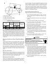
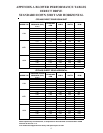
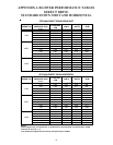
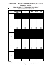
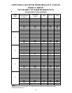
REFRIGERATION PERFORMANCE CHECK
Under normal summertime (full load) operating conditions,
superheat should be between 8°F and 12°F and sub-cooling
measured at the condenser outlet should be 15°F (nominal).
A 25°F to 35°F temperature difference should exist between
the entering condenser air and the temperature correspond-
ing to the compressor saturated discharge pressure. Check
that compressor RLA corresponds to values shown in Ap-
pendix C. RLA draw can be much lower than values listed at
low load conditions and low ambient condensing tempera-
tures. Values in Appendix C can slightly exceed at high load
conditions and high ambient condensing temperatures.
HEAT PUMP OPERATION
COOLING CYCLE
When the heat pump is in the cooling cycle, it operates ex-
actly as a Summer Air Conditioner unit. In this mode, all the
charts and data for service that apply to summer air condi-
tioning apply to the heat pump. Most apply on the heating
cycle except that “condenser” becomes “evaporator”, “evapo-
rator” becomes “condenser”, “cooling” becomes “heating”.
HEATING CYCLE
The heat pump operates in the heating cycle by redirecting
refrigerant flow through the refrigerant circuit external to the
compressor. This is accomplished with through the reversing
valve. Hot discharge vapor from the compressor is directed
to the indoor coil (evaporator on the cooling cycle) where the
heat is removed, and the vapor condenses to liquid. It then
goes through the expansion device to the outdoor coil (con-
denser on the cooling cycle) where the liquid is evaporated,
and the vapor goes to the compressor.
When the solenoid valve coil is operated either from heating
to cooling or vice versa, the piston in the reversing valve to
the low pressure (high pressure) reverse positions in the re-
versing valve.
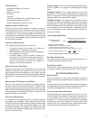
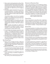
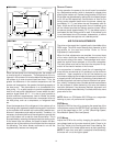
The following figures show a schematic of a heat pump on
the cooling cycle and the heating cycle. In addition to a re-
versing valve, a heat pump is equipped with an expansion
device and check valve for the indoor coil, and similar equip-
ment for the outdoor coil. It is also provided with a defrost
control system.
The expansion devices are flowrator distributors and perform
the same function on the heating cycle as on the cooling cycle.
The flowrator distributors also act as check valves to allow
for the reverse of refrigerant flow.