


Model HUM-FP
INSTALLATION INSTRUCTIONS (cont'd.)
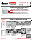
WARNINGS:
Shut off power before wiring.
DO NOT wire the Model HUM-FP
KXPLGLÀHUWRDFLUFXLWERDUG
UNLESS the board connections are
120 VAC. If, and only if, they are 120
VAC, install a receptacle and wire it
to the board connections. Plug the
KXPLGLÀHULQWRWKHUHFHSWDFOH
DO NOT, under any circumstances,
wire the yellow solenoid wires
to the curcuit board, or any other
power source!
Wiring
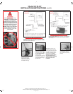
Diagram A
Wiring
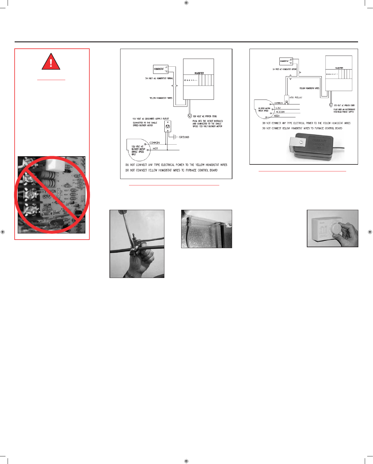
Diagram B
13
14
12. Tap into the water
supply line using the
saddle valve provided.
Follow the directions on
the saddle valve bag.
13. Connect copper tub-
ing from the saddle valve
to the solenoid valve. (Do
not use plastic tubing.)
Check for leaks.
The saddle valve must be
fully opened or closed. Do
not use the valve to regu-
ODWHZDWHUÁRZ
14. Attach a 1/2" I.D. vinyl
hose and clamp to carry the
ÁXVKLQJZDWHUIURPWKHXQLWWR
the drain. Be sure the drain
hose has a constant pitch to
WKHÁRRUGUDLQTo avoid
GDPDJHWRWKHGUDLQÀWWLQJ
do not use solvent type
adhesives when connecting
the plastic hose to the
KXPLGLÀHU
15. Test operation. Check
for water leaks. Be sure
the humidistat is operating
properly.
11a. Wiring Diagram A: Single-Speed Blower.
For wiring with a 120 VAC single-speed blower, locate
the blower motor junction box. Wire in a receptacle for the
9
$&KXPLGLÀHUSOXJ7KLVZLOOFRRUGLQDWHWKHKXPLGLÀHU
and furnace system operations.
11b. Wiring Diagram B: Multi-Speed Blower.
For wiring with a multi-speed blower, use an HUM-A50
Current Sensing Relay with an existing or independently
ZLUHGÀHOGLQVWDOOHG9
$&RXWOHW3OXJWKHKXPLGLÀHU
into the outlet.
IO-310 05/06
Goodman® is a registered trademark of Goodman Manufacturing Company, L. P.
Amana® is a trademark of Maytag Corporation and is used under license to Goodman Company, L. P.
All rights reserved.