


10
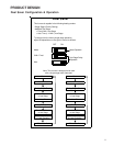
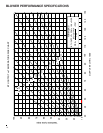
PRODUCT DESIGN
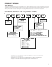
Thermostats:
NOTE: Complete lineup of thermostats can be found in the Thermostat Specification Sheets.
Filters:
Filters are required with this furnace and must be provided by the installer. The filters used must comply with UL900 or
CAN/ULCS111 standards. Installing this furnace without filters will void the unit warranty.
This furnace has provisions for the installation of return air filters at the side and/or bottom return. The furnace will
accommodate the following filter sizes depending on cabinet size:
Refer to Minimum Filter Area tables to determine filter area requirement. NOTE: Filters can also be installed elsewhere in
the duct system such as a central return.
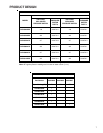
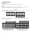
Upflow Filters
Disposable Minimum Filter Area (in
2
)
[Based on a 300 ft/min filter face velocity]
*Minimum filter area dictated by heating airflow requirement.
Permanent Minimum Filter Area (in
2
)
[Based on 600 ft/min filter face velocity]
*Minimum filter area dictated by heating airflow requirement.
600 800 1000 1200 1400 1600 2000
0453BXA* 194* 194* 240 288 --- --- ---
0703BXA* --- 324* 324* 324* 336 --- ---
0704CXA* --- --- 291* 291* 336 384 ---
0904CXA* --- --- 432* 432* 432* 432* ---
0905DXA* --- --- --- 388* 388* 388* 480
1155DXA* --- --- --- 486* 486* 486* 486*
Input__Airflow
COOLING AIRFLOW REQUIREMENT (CFM)
600 800 1000 1200 1400 1600 2000
0453BXA* 388* 388* 480 576 --- --- ---
0703BXA* --- 647* 647* 647* 672 --- ---
0704CXA* --- --- 583* 583* 672 768 ---
0904CXA* --- --- 863* 863* 863* 863* ---
0905DXA* --- --- --- 777* 777* 777* 960
1155DXA* --- --- --- 971* 971* 971* 971*
COOLING AIRFLOW REQUIREMENT (CFM)
Input__Airflow
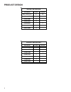
Cabinet
Width
(in.)
Nominal
Filter Size
(in.)
Approx.
Flow Area
(in
2
)
Cabinet
Width
(in.)
Nominal
Filter Size
(in.)
Approx.
Flow Area
(in
2
)
All 16 x 25 x 1 400 17-1/2 14 x 25 x 1 350
21 16 x 25 x 1 400
24-1/2 20 x 25 x 1 500
Side Return(s) Bottom Return