


18
5
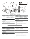
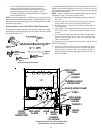
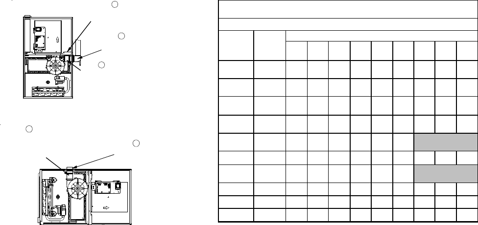
A
DDITIONAL PLUG
FROM DRAIN KIT
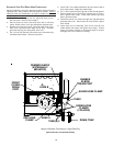
7
EXTERNALLY
MOUNT
RUBBER ELBOW
6
SECURE TO
ID BLOWER WITH
RUBBER COUPLING
AND HOSE
CLAMPS
COUNTERFLOW/UPRIGHT
(UPFLOW SIMILAR)
UPFLOW/HORIZONTAL
(COUNTERFLOW SIMILAR)
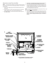
6
SECURE TO
ID BLOWER WITH
RUBBER COUPLING
AND HOSE
CLAMPS
6
SECURE TO
CABINET WITH
SCREWS
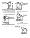
Alternate Vent/Flue Location
NON-DIRECT VENT (SINGLE PIPE) PIPING
Non-direct vent installations require only a vent/flue pipe. The vent
pipe can be run horizontally with an exit through the side of the
building or run vertically with an exit through the roof of the building.
The vent can also be run through an existing unused chimney;
however, it must extend a minimum of 12 inches above the top of
the chimney. The space between the vent pipe and the chimney
must be closed with a weather-tight, corrosion-resistant flashing.
For details concerning connection of the vent/flue pipe to the fur-
nace, refer to Vent/Flue Pipe and Combustion Air - Standard Fur-
nace Connections or Alternate Furnace Connections for specific
details. Refer to the following Non-Direct Vent (Single Pipe) Piping
- Vent/Flue Pipe Terminations for specific details on termination
construction.
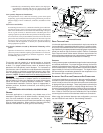
Although non-direct vent installations do not require a combustion
air intake pipe, a minimum of one 90° elbow should be attached to
the furnace’s combustion air intake if: an upright installation uses
the standard intake location. This elbow will guard against inad-
vertent blockage of the air intake.
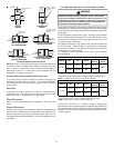
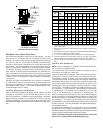
VENT/FLUE PIPE LENGTHS AND DIAMETERS
Refer to the following table for applicable length, elbows, and pipe
diameter for construction of the vent/flue pipe system of a non-
direct vent installation. In addition to the vent/flue pipe, a single 90°
elbow should be secured to the combustion air intake to prevent
inadvertent blockage. The tee used in the vent/flue termination must
be included when determining the number of elbows in the piping sys-
tem.
012345678
40,000
2
or 2 1/2
1009590858075706560
45,000
2
or 2 1/2
250 245 240 235 230 225 220 215 210
60,000
2
or 2 1/2
110105100959085807570
70,000
2
or 2 1/2
220 215 210 205 200 195 190 185 180
80,000
2
or 2 1/2
35 30 25 20 15 10
80,000 3 132 125 118 111 104 97 90 83 76
90,000
2
or 2 1/2
45 40 35 30 25 20
90,000 3 147 140 133 126 119 112 105 98 91
100,000 3 98 91 84 77 70 63 56 49 42
115,000 3 140 133 126 119 112 105 98 91 84
Not Applicable
Not Applicable
*MH95/ACSH96/AMEH96/GCH95/GME95
Direct Vent (2 - Pipe) and Non-Direct Vent (1- Pipe)
(6)
Maximum Allowable Length of Vent/Flue Pipe & Combustion Air Pipe (ft)
(1) (2)
Unit Input
(Btu)
Pipe
Size
(4)
(in.)
Number of Elbows
(3) (5)
1) Maximum allowable limits listed on individual lengths for inlet and flue and
NOT a combination.
2) Minimum requirement for each vent pipe is five (5) feet in length and one
elbow/tee.
3) Tee used in the vent/flue termination must be included when determining
the number of elbows in the piping system.
4) 2 1/2” or 3” diameter pipe can be used in place of 2” diameter pipe.
5) Increased Clearance Configurations using (2) 45 deg.
Long Sweep
elbows should be considered equivalent to one 90 deg. elbow.
6) One 90° elbow should be secured to the combustion air intake connec-
tion.
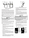
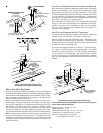
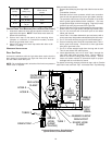
VENT/FLUE PIPE TERMINATIONS
NOTE: If either a 90 degree or 45 degree elbow is used for termina-
tion, it must be pointed downward.
The vent/flue pipe may terminate vertically, as through a roof, or
horizontally, as through an outside wall.
Vertical vent/flue pipe terminations should be as shown in the fol-
lowing figure. Refer to Vent/Flue Pipe and Combustion Air Pipe -
Termination Locations for details concerning location restrictions.
The penetration of the vent through the roof must be sealed tight
with proper flashing such as is used with a plastic plumbing vent.
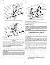
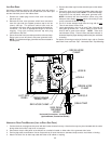
Horizontal vent/flue pipe terminations should be as shown in the
following figure. Refer to Section IX, Vent/Flue Pipe and Combus-
tion Air Pipe - Termination Locations for details concerning loca-
tion restrictions. A 2 3/8” diameter wall penetration is required for
2” diameter pipe. A 3” diameter hole is required for a 2 1/2” pipe
and a 3 1/2” diameter hole is required for 3” diameter pipe. To
secure the pipe passing through the wall and prohibit damage to
piping connections, a coupling should be installed on either side
of the wall and solvent cemented to a length of pipe connecting the
two couplings. The length of pipe should be the wall thickness
plus the depth of the socket fittings to be installed on the inside and
outside of the wall. The wall penetration should be sealed with sili-
cone caulking material.
In a basement installation, the vent/flue pipe can be run between
joist spaces. If the vent pipe must go below a joist and then up into
the last joist space to penetrate the header, two 45° elbows should be
used to reach the header rather than two 90° elbows.
NOTE: Terminate both pipes in the same pressure zone (same
side of roof, no major obstacles between pipes, etc.)