


9
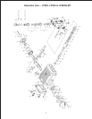
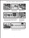
To Dismantle Gear End
After removing valve casing (43) and plunger pipe (29B), drain oil. Remove gear cover (4) and bearing cover
(14). Loosen connecting rod screws (24A) and push the front of the connecting rod (24) forward as far as
possible into the crosshead guide.
IMPORTANT! Connecting rods (24) are marked for identification. Do not twist connecting rod halves.
Connecting rod is to be reinstalled in the same position on shaft journals.
Turning the crankshaft (22) slightly, hit it out carefully to the side with a rubber hammer.
IMPORTANT! Do not bend the connecting rod (24) shanks. Check crankshaft (22) and connecting rod
(24) surfaces, radial shaft seals (15) and taper roller bearings (20).
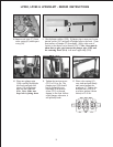
To Reassemble
Using a soft tool, press in the outer bearing ring until the outer edge lines up with the outer edge of the bearing
hole. Remove bearing cover (14) together with radial shaft seal (15) and o-ring (16). Fit crankshaft (22)
through bearing hole on the opposite side. Press in outer bearing and tighten it inwards with the bearing cover,
keeping the crankshaft in vertical position and turning slowly so that the taper rollers of the bearings touch the
edge of the outer bearing ring. Adjust axial bearing clearance to at least 0.1mm and maximum 0.15mm by
placing fitting discs (20A and 20B) under the bearing cover.
IMPORTANT! After assembly has been completed, the crankshaft should turn easily with very little clear-
ance. Tighten connecting rod screws (24A) to 310 in.-lbs.
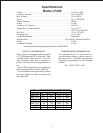
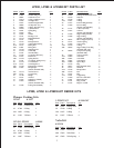
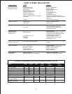
Position Item# Description Torque Amount
24 13340 Inner Hex Screw, Connecting Rod 310 in.-lbs.
29C 07131 Tension Screw, Plunger 310 in.-lbs.
48 07156 Plug, Discharge 107 ft.-lbs.
49A 07158 Hexagon Nut, Stud Bolts 59 ft.-lbs.
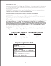
LP200, LP250 & LP250W-MT TORQUE SPECIFICATIONS
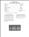
Pump Mounting Selection Guide
Bushings
06496 - 35mm H Bushing
Pulley & Sheaves
07165 - 12.75 Cast Iron - 4 gr. - AB Section
Rails
07357 - Plated Steel Channel Rails
(L=11.75xW1.88xH=3.00)