


6
REPAIR INSTRUCTIONS - Model LP700
VALVE REPLACEMENT
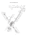
1) Discharge Valves: Screw out 8 x hexagon screw (54), remove cover (51). Screw hexagon screw (54) into thread of plug (50) and
pull out plug. Using a clipring pliers, remove spring tension cup (44A) and valve seat (44D). If necessary, use a dia 12 pull-out
tool to remove valve seat. Cheack parts, and replace if worn.
2) Check O-rings (40/44E) and support rings (41/44F) and replace as necessary.
3) Tighten hexagon screws (54) TO 59 ft. lbs.
4) Suction Valves: Unscrew 8 x nut (47), remove valve casing (45) from seal sleeves (42). Using two screwdrivers, lever out seal
case (42) from valve casing. Remove Spring tension cup (44A) and valve seat (44D) with a clipring pliers. If necessary, use a dia
12 pull-out tool to remove valve seat. Check parts, and replace if worn.
5) Check O-rings (40/44E) and support rings (41/44F) and replace as necessary.
SEAL AND PLUNGER REPLACEMENT
1) Unscrew the 8 x nut (47), remove valve casing by pulling it out to the front. Remove seal sleeve (35). Remove tension spring
(38A) and seal parts (36-38) from seal sleeve. Check plunger surface and seals (37). Replace worn parts.
2) After removing clipring (32) and support ring (33), check leakage seal (33A) and replace if necessary.
3) If the surface of the plunger is worn, screw out the plunger (29) with a size 13 tool. Clean centring and front surface of crosshead
with plunger (25).
4) Thread new plunger carefully through oiled seals in seal sleeve. Coat thread of new plunger lightly with suitable bonding agent
(locktite).
5) Then insert seal sleeve with plunger into crankcase guide. Crank drive until plunger with crosshead (25) pushes against plunger
(29). Tighten plunger (29) to 22 ft. lbs. using a size 13 torque wrench.
NOTE: The leakage seal (39) has to be installed so that its cut-outs cover the 3 mm dia. bores of the seal sleeves (35) as well as the 3
mm dia. drip-return bores of the valve casing.
DISASSEMBLY OF CRANKCASE
1) Remove valve casing (#43) and plunger pipe (#28B), drain oil.
2) Screw off gear cover (#4) and bearing cover (#14).
3) Remove connecting rod screws (#24) and push the front of connecting rod forward as far as possible. Remove back halves of
connecting rods, note which position from which they came from.
4) Turning the crankshaft slightly, carefully hit on side of crankshaft (#22) with a rubber mallet until crankshaft is loose.
5) Check crankshaft and bearing for damage, replace if needed.
REASSEMBLY
6) Using a soft tool, press in the outer bearing ring until the outer edge lines up with the outer edge of crankcase (#1). Attach bearing
cover (#14) with shaft seal and o-ring (#16) in place. Fit crankshaft through bearing hole on the opposite side. Press in bearing
with bearing cover, keeping the shaft in a horizontal position and turning it slowly so that taper rollers touch the edge of outer
bearing ring.
7) Adjust axial bearing clearance to at least .004" and maximum at .006 by placing fitting discs (#20A & 20B) under the bearing
cover.
8) After assembly the shaft should turn easily with very little clearance.
9) Bolt connecting rod halves together making sure they are replaced in the same position from which they came from. Tighten
connecting rod screws to 264 in.-lbs.