


7
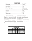
REPAIR INSTRUCTION - LP350, LP400, LP450
VALVE REPLACEMENT
1) With a 30mm wrench remove the three (3) tension plugs (#48) from top of valve casing (43).
2) Remove discharge and inlet valves (#46), pulling them upwards out of the valve casing. It maybe necessary to use a slide hammer
tool.
3) With the valve assembly pointed down, place a dowel rod through the top of valve cage. Hold assembly in hand and tap end of
dowel sharply with mallet until assembly pops free.
4) Inspect valve seats (#46A) and valve plates (#46B) for damage and replace if needed.
5) Check valve casing (#43) surfaces for damage.
6) Replace o-rings (#44A) and reinstall valve assemblies into valve casing. (Lubricate o-rings before installation.)
7) Replace tension plugs (#48) and tighten them securely.
SEAL AND PLUNGER REPLACEMENT
1) Remove the eight (8) manifold nuts and washers (#49A,B) using a 19mm wrench and pull off valve casing (#43). If needed, tap
valve casing with a rubber mallet to remove it.
2) Pull seal sleeve (#35) out of crankcase guides.
3) Remove seal case (#37) from seal sleeve.
4) Check plunger surface for wear and pitting. If none is found, proceed to step eleven.
5) If plunger (#29B) is worn, remove tension screw (#29C) with a 17mm wrench. Clean tension screw with wire brush to remove
any old locktite.
6) Discard copper gasket (#29D) and replace with new.
7) Clean the front surface of plunger/ crosshead assembly (#25).
8) Install new plunger (#29B) onto plunger/ crosshead assembly.
9) Put some locktite on both surfaces of copper gasket (#29D) and tension screw threads (#29C).
10) Secure plunger in place with tension screw (#29C) and gasket (#29D) and tighten to 33 ft. lbs.
11) Remove v-sleeves (#40) and o-ring (#41) for seal case and replace with new. Lubricate parts before reinstalling.
12) Replace seal case (#35) and seal sleeve (#37) into valve casing. Replace nuts and washers (#49A,B) and
tighten to 59 ft. lbs.
DISASSEMBLY OF CRANKCASE
1) Remove valve casing (#43) and plunger pipe (#28B), drain oil.
2) Screw off gear cover (#4) and bearing cover (#14).
3) Remove connecting rod screws (#24) and push the front of connecting rod forward as far as possible. Remove back halves of
connecting rods, note which position from which they came from.
4) Turning the crankshaft slightly, carefully hit on side of crankshaft (#22) with a rubber mallet until crankshaft is loose.
5) Check crankshaft and bearing for damage, replace if needed.
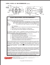
REASSEMBLY
6) Using a soft tool, press in the outer bearing ring until the outer edge lines up with the outer edge of crankcase (#1). Attach bearing
cover (#14) with shaft seal and o-ring (#16) in place. Fit crankshaft through bearing hole on the opposite side. Press in bearing
with bearing cover, keeping the shaft in a horizontal position and turning it slowly so that taper rollers touch the edge of outer
bearing ring.
7) Adjust axial bearing clearance to at least .004" and maximum at .006 by placing fitting discs (#20A & 20B) under the bearing
cover.
8) After assembly the shaft should turn easily with very little clearance.
9) Bolt connecting rod halves together making sure they are replaced in the same position from which they came from. Tighten
connecting rod screws to 264 in.-lbs.
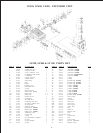
Valve Kit #09196
Qty Part # Description
1 7064 Valve seat
1 7063 Valve plate
1 7062 Valve spring
Packing Kit, LP350 #09233
Qty Part # Description
6 13016 V-sleeve
3 7150 O-ring
3 13012 O-ring
3 7140 O-ring
Packing Kit, LP400 #09309
Qty Part # Description
6 06083 V-sleeve
3 13349 O-ring
3 13012 O-ring
3 7140 O-ring
Packing Kit LP450 #09234
Qty Part # Description
6 13015 V-Sleeve
3 7102 O-ring
3 13012 O-ring
3 7140 O-ring
TORQUE SPECIFICATIONS
Position Description Torque Amount
24 Connecting Rod 264 in.-lbs.
29C Tensioning Screw 33 ft.-lbs.
49A Hexagon Nut 59 ft.-lbs.
LP350, LP400 & LP450 KITS