


8
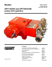
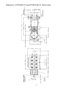
GP7145GB-2.4 and GP7255AGB-2.4 Repair Instructions
TO CHECK VALVES
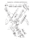
Loosen plugs (58), take out tension spring (57) and then remove the complete valve assembly (51) with
either a valve tool or an M16 hexagon screw. To remove the valve adapter (56) and tension spring (57),
use a pullout tool size 5. To disassemble valve assembly, carefully hit the top of the valve plate (51C)
with a metal dowel and press the valve seat (51E) out of the valve adapter (56). Check sealing surfaces
and replace worn parts. Check O-rings and support rings. Tighten plugs (58) to 107 ft.-lbs. (145 NM).
TO CHECK SEALS AND PLUNGER PIPE
Loosen nuts (49A) and remove pump head (50). Separate the plunger connection (36A) from the cross-
head (25) by means of two open-end wrenches (size 22mm and 27mm). Pull seal sleeves (39) out of
their fittings in the crankcase (1). Take the seal case (38) out of the seal sleeve (39). Examine the
plunger parts (36A-36D), seals (42 & 39A) and O-rings (38A & 38B). When replacing the plunger pipe
(36B), tighten tension screws (36C) to 30 ft. lbs. (40 NM). Replace worn parts; grease seals with Sili-
cone before installing.
CAUTION: Don't loosen the 3 plunger connections (36A) before the valve casing has been removed
otherwise the tension screw (36C) could hit against the valve adapter (56) when the pump
is being turned. Seal life can be increased if the pre-tensioning allows for a little leakage.
This assists lubrication and keeps the seals cool. It is therefore not necessary to replace
seals before the leakage becomes too heavy and causes output and operating pressure to
drop.
MOUNTING VALVE CASING
Check O-rings (38A & 38B) on the seal case (38). Clean surfaces of seal sleeves in gear box and sealing
surfaces of valve casing (50). Push the valve casing carefully on the O-rings of the seal case and center-
ing studs (50A). Tighten nuts (49A) to 103 ft. lbs. (140 NM).
TO DISASSEMBLE GEAR
Take out plunger (36) and seal sleeves (39) as described above. Drain the oil. After removing the circlip
ring (33B), lever out seal retainer (33) with a screw driver. Check seals (32 & 33A) and surfaces of
crosshead (25) .
Important! Seal (32) must always be installed so that the seal-lip on the inside diameter faces the oil.
Possible axial float of the seal retainer (33) should be compensated with the shims (33C).
Remove the crankcase cover (4). Loosen inner hexagon screws on the connecting rods (24).
Note: Connecting rods are marked for identification. Do not twist connecting rod halves. Each con-
necting rod is to be reinstalled in the same position (and orientation) on the crankshaft journals.
Push the connecting rod halves as far into the crosshead guide as possible. Take out the bearing cover
(14).