


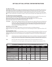
7
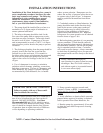
TO CHECK VALVES
Lossen plugs (58), take out tension spring (57) and then remove the complete valve (51) with either a valve tool or an
M16 hexagon screw. Remove valve adapter (56) and tension spring (57) with pull-out tool size 5. There is an O-ring
(51G) under both the suction and the discharge valve each of which can be removed with a bent piece of wire.To
disassemble valve hit the top of the valve plate (C) carefully with a bolt and press the valve seat (A) out of the spacer
pipe (E). Check sealing surfaces and replace worn parts. Check O-rings and support rings.Tighten plugs (58) to 107 ft.
lbs.
TO CHECK SEALS AND PLUNGER PIPE
Loosen nuts (49A) and remove pump head. Separate plunger connection (36A) from crosshead (25) by means of two
open-end wrenches (size 22 and 27). Pull seal sleeves (39) out of their fittings in the crankcase.
Take seal case (38) out of seal sleeve (39). Examine plunger parts (36A-36D), seals (42,39A) and O-rings.
When replacing plunger pipe (36B), tighten tension screws (36C) to 30 ft. lbs.
Replace worn parts; grease seals with Silicone before installing.
CAUTION: Don't loosen the 3 plunger connections (36A) before the valve casing has been removed otherwise the
tension screw (36C) could hit against the spacer pipe (51E) when the pump is being turned. Seal life
can be increased if the pretensioning allows for a little leakage. This assists lubrication and keeps the
seals cool. It is therefore not necessary to replace seals before the leakage becomes too heavy and
causes output and operating pressure to drop.
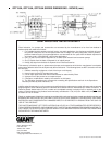
MOUNTING VALVE CASING
Check O-rings on seal case (38). Clean surfaces of seal sleeves in gear box and sealing surfaces of
valve casing. Push valve casing carefully on O-rings of seal case and centering studs (50A). Tighten nuts (49A) to 103
ft. lbs.
TO DISASSEMBLE GEAR
Take out plunger and seal sleeves as described above. Drain oil. After removing the circleclip ring (33B), lever out seal
retainer (33) with a screw driver. Check seals (32, 32A, 33A) and surfaces of crosshead. Remove crankcase cover (4).
Loosen inner hexagon screws on the connecting rods (24) and push con rod halves as far into the crosshead guide as
possible.
Note: Connecting rods are marked for identification. Do not twist con rod halves. Con rod is to be reinstalled
in the same position on shaft journals.Check surfaces of connecing rod and crankshaft (22) take out
bearing cover to one side and push out crankshaft taking particular care that the conrod doesn't gt bent.
Note: Seal (32A) must always be installed so taht the seat up on the inside diameter faces the oil.
Reassemble in revers order: Regulate axial bearing clearance minimum 0.1mm, maximum 0.15-by
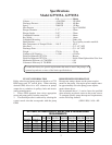
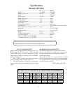
GP7150A, GP7155A, GP7255A REPAIR INSTRUCTIONS
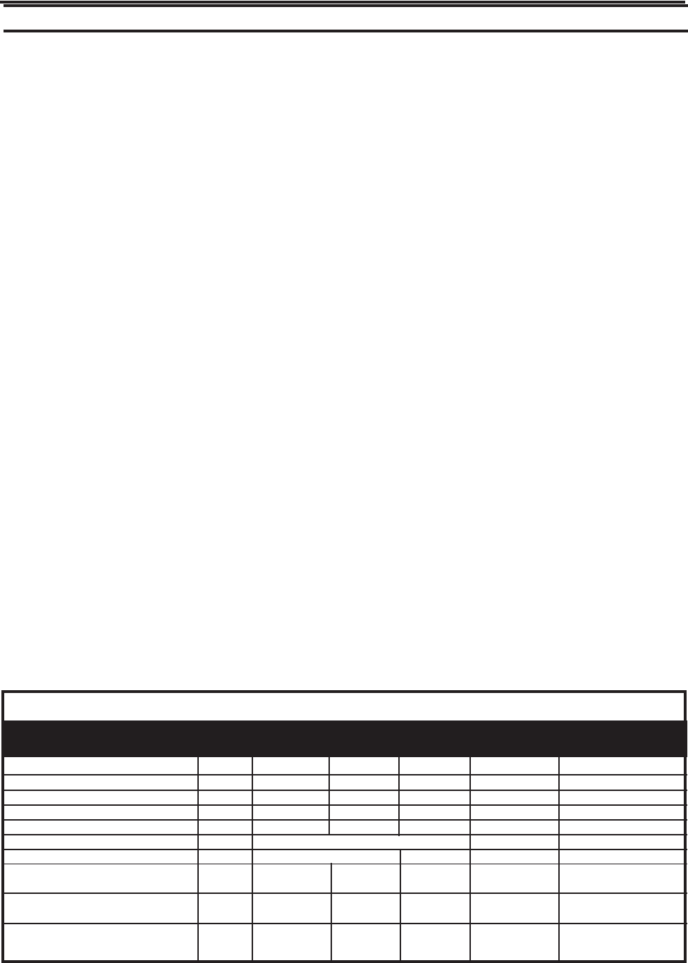
Preventative Maintenance Check-List & Recommended Spare Part List
Check Daily Weekly 50hr Every Every Every
500 hr 1500 hr 3000hrs
Oil Level / Quality X
Oil Leaks X
Water Leaks X
Belts, Pulley X
Plumbing X
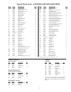
Recommended Spare Part
Oil Change (p/n 01154) X
X
Plunger Packing Kits(1 kit/Pump)
See page 5 for kit list
Oil Seal Kit ( 1 kit/Pump
See page 5 for kit list)
Valve Assembly Kit ( 1 kit/pump)
See page 5 for kit list
X
X
X