


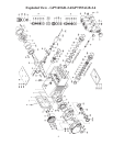

TO DISMANTLE REDUCTION GEAR
Remove screws (G4). Using screwing two screws into the both thread bores, press off the gear cover
(G2). Remove screw (G11) and take off the spacer ring (G7) and tension disc (G10). Push the cogwheel
(G9) off the shaft by screwing two screws into both thread bores. Finally, take the crankshaft (22) out of
the crankcase by tapping it towards the bearing cover side using a rubber hammer.
Check the surfaces of connecting rods (24), crankshaft (22) and crossheads (25). Check the surfaces of
the crosshead guides in the crankcase for any unevenness.
Reassemble in reverse order. Regulate axial bearing clearance to a minimum of 0.1mm and a maximum
0.15mm by means of fitting discs (20A). Insert the crankshaft by passing it through on the bearing cover
side. Press in the outer bearing ring (20). The crankshaft should turn easily and with little clearance.
Fit the bearing cover (14) and tighten screws (24) to 30 ft.-lbs. (40 NM).
Important! The connecting rod has to be able to slightly move sidewise at the crankshaft journal.
Heat the ball bearings (G13) before pressing them onto the pinion (G12). Slightly press the cogwheel
(G9) onto the crankshaft, so that the pinion (G12) together with the bearing (G13) can still be inserted.
When mounting, place the pinion (G12) onto the cogwheel so that they correctly interlock. Carefully tap
the cogwheel and the pinion simultaneously onto the crankshaft and into the bearing seat.
Fit tension disc (G10), and spacer ring (G7) and tighten screw (G11) with Loctite.
Fit seal (17) on to the cylindrical pins (G3).
Push the gear cover (G2) carefully on to the bearing (G13). make sure the radial shaft seal (G17) does
not get damaged during fitting on to the pinion.
Important! Before putting into operation again, turn the reduction gear shaft by hand at least four full
turns to make sure that the gear is correctly aligned.
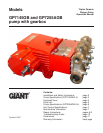
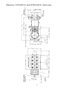
GP7145GB-2.4 and GP7255AGB-2.4 Repair Instructions
9