6
GP7124A REPAIR INSTRUCTIONS
NOTE: Always take time to lubricate all metal and non-metal parts with a light film of oil
before reassembling. This step will help ensure proper fit, at the same time protecting
the pump non-metal parts (elastomers) from cutting and scoring.
TO CHECK VALVES
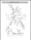
Lossen screws (58C), take plugs (58) out of valve casing with two screws. Take out complete valve (51)
using either tool (part #07662) or stud bolt. Valve seats (51C and 52C) are pressed out of spacer pipe
(51F) by hitting the valve plate (51D) with a bolt. Check surfaces of valve plate, valve seat, O-rings (51B,
58A) and replace worn parts.
CAUTION: When reassembling: The suction valve seat (51C) is 1mm smaller in diameter than the
discharge valve seat (52C). Suction valve seats are marked "S" and always have to be
installed first. Discharge valve seats are marked "P" and are always tobe installed on top of
suction valve. Plugs (58) are to be tensioned down evenly with screws (58C) and crosswise
at 210NM.
TO CHECK SEALS AND PLUNGER PIPE
Loosen nuts (49A) and remove pump head. Separate plunger (36) from crosshead (25) by means of two
open-end wrenches (size 22 and 27). Pull seal sleeves (38) out of their fittings in the crankcase. Take seal
case (39) out of seal sleeve (38). Take seal-pack (40-43) out of seal sleeve. After removing the circlip ring
(44) take seal-pack (43A-C) out of seal sleeve (38).
Examine plunger (36) and seals (40,42,43B).
When replacing plunger (36), tighten new plunger to 26 ft.lbs.
Replace worn parts; grease seals with Silicone before installing.
CAUTION: Don't loosen the 3 plunger (36) before the valve casing has been removed otherwise the
plunger (36) could hit against the spacer pipe (51F) when the pump is being turned.
Seal life can be increased if the pretensioning allows for a little leakage. This assists lubrica-
tion and keeps the seals cool. It is therefore not necessary to replace seals before the leak-
age becomes too heavy and causes output and operating pressure to drop.


